31
1
ON
2 3 4 5 6 7
ON
OFF
1 2 3 4 5 6 7
DIP#4
ON Push-to-open operation.
OFF Pull-to-open operation (factory setting).
GRN
BLK
RED
RECEIVER
COM COM
CYCLE
CLOSE
SAFETY
EXIT
OPEN
SHADOW
LOO
P
CLOSE
EDGE
OPEN
EDGE
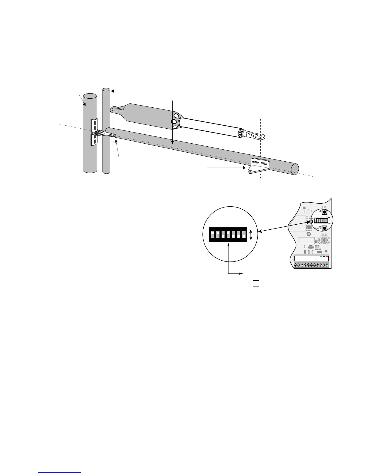
Step 3
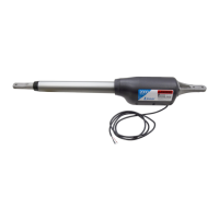
With the gate in the fully closed position and the operator retracted, swing the operator to the gate. Mark reference points for
bolt holes on gate cross member through middle of gate bracket slots. The operator must be level. (Some vertical adjustment
is possible by sliding the post bracket assembly up and down.) Drill
3
/8" holes into the gate cross member as marked. Fasten
gate bracket to cross member using (2) 3/8" x 3" bolts, washers, lock washers, and nuts. Attach the operator to the post
bracket assembly and gate bracket using clevis pins, bushings, and hairpins clips.
Step 4
Make sure the control box power switch is OFF. Use a small
screwdriver to move the Number 4 DIP switch from the factory
setting (OFF / Pull-To-Open) to ON for Push-To-Open. Turn
power switch ON. The control board is now configured to push
the gate open.
Setting the Open Position Limit
Step 1
Confirm that the power switch is in the ON position, and the gate is in the CLOSED POSITION.
Step 2
Activate your operator by pressing the entry transmitter button. Your gate should now be moving from the closed position
toward the open position. Prepare to STOP gate by pressing the entry transmitter button again when the gate reaches the
desired open position. This step may be repeated until desired close position is achieved. Once the desired OPEN position has
been achieved, proceed to Step 3.
Operator
Fence Post
Gate Post and Gate Cross Member
(In Closed Position)
POST PIVOT BRACKET level with the
horizontal surface of the GATE BRACKET
LEVEL
LEVEL
LEVEL