GRS-6052A/6032A OSCILLOSCOPE
USER MANUAL
⎯ ⎯
40
5-4.Function Check
When you start to check the operation of your oscilloscope, proceed the
following instruction:
1. Install the ×10 probes onto CH1 and CH2 inputs.
2. Connect the probe tips to the CAL test point of the oscilloscope.
3. Set the oscilloscope controls to display both channels:
VERTICAL: VOLTS/DIV 0.2V
COUPLING DC
ALT/CHOP CHOP
HORIZONTAL:
TIME/DIV 0.5ms
TRIGGER: MODE ATO
SOURCE VERT
COUPLING AC
SLOPE
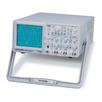
The figure 5-3 below illustrates a satisfactory display. The waveform should
be approximately 0.5Vp-p at a frequency of 1kHz that confirms the vertical
and horizontal deflection function of the oscilloscope.
Figure 5-3 Function Check
GRS-6052A/6032A OSCILLOSCOPE
USER MANUAL
⎯ ⎯
41
4. Set both CH1 and CH2 COUPLING to GND.
5. Use the CH1 and CH2 POSITION controls to align both traces on the center
graticule.
6. Open the CH2 INV by pressing and holding the pushbutton.
7. Set to the ADD mode by pressing the ADD pushbutton briefly.
8. Set both CH1 and CH2 COUPLING to DC.
9. The figure 5-4 below shows a satisfactory display. The display will show a
flat trace located on the center graticule that confirms the channel balance
and ADD offset function.
Figure 5-4 ADD mode
10. Turn off the ADD mode by pressing the ADD pushbutton briefly.
11. Turn off the CH2 INV by pressing and holding the pushbutton.
www. .com
information@itm.com1.800.561.8187
 Loading...