6
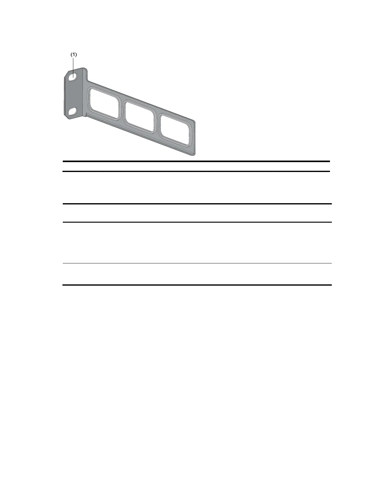
Figure 3 Appearance of a rear mounting bracket
(1) Screw hole for
attachin
the mountin
bracket to the cabinet (Use one M6 screw)
For the selection of front and rear mounting brackets, see Table 4.
Table 4 Selection of mounting bracket for the S5120-EI Switch Series
Model Dimensions (H × W × D)
Configuration type of
front mountin
bracket
Configuration type of
rear mountin
bracket
S5120-28C-EI
S5120-52C-EI
S5120-24P-EI
S5120-48P-EI
43.6 × 440 × 300 mm
(1.72 × 17.32 × 11.81 in)
Standard N/A
S5120-28C-PWR-EI
S5120-52C-PWR-EI
43.6 × 440 × 420 mm
(1.72 × 17.32 × 16.54 in)
Standard Standard
Rack-mounting by using front mounting brackets
O n ly the S 512 0 -28 C - E I , S 512 0 - 52 C - E I, S 512 0 -24 P-E I , a n d S 512 0 - 48 P- E I s u p p o r t i n s t a l l a t i o n by u s in g
front mounting brackets.
To mount a switch into a 19-inch standard cabinet:
1. Wear an ESD-preventive wrist strap and make sure it makes good skin contact and is well
grounded.
2. Verify the grounding and stability of the rack.
3. Unpack the screws which are packed together with the front mounting brackets, and attach one
end of mounting brackets to the switch, as shown in Figure 4.

 Loading...


