8
4. Unpack the screws which are packed together with the front mounting brackets, and attach one
end of mounting brackets to the switch, as shown in Figure 4.
5. Place the
switch on the rack-shelf horizontally, slide the rack-shelf into the rack, and attach the
other end of mounting brackets to the front brackets with crews and cage nuts, as shown in Figure
5.
Rack-mounting by using front and rear mounting brackets
Only the S5120-28C-PWR-EI and S5120-52C-PWR-EI support installation by using front and rear
mounting brackets.
To install the switch into a 19-inch standard rack:
1. Wear an ESD-preventive wrist strap and make sure it makes good skin contact and is well
grounded.
2. Verify the grounding and stability of the cabinet.
3. Unpack the screws which are packed together with the front mounting brackets, and attach one
end of mounting brackets to the switch, as shown in Figure 4.
4. Unpac
k the load-bearing screws (packed together with the rear mounting brackets) and place
them in a proper position on the sides of the switch, as shown in Figure 6.
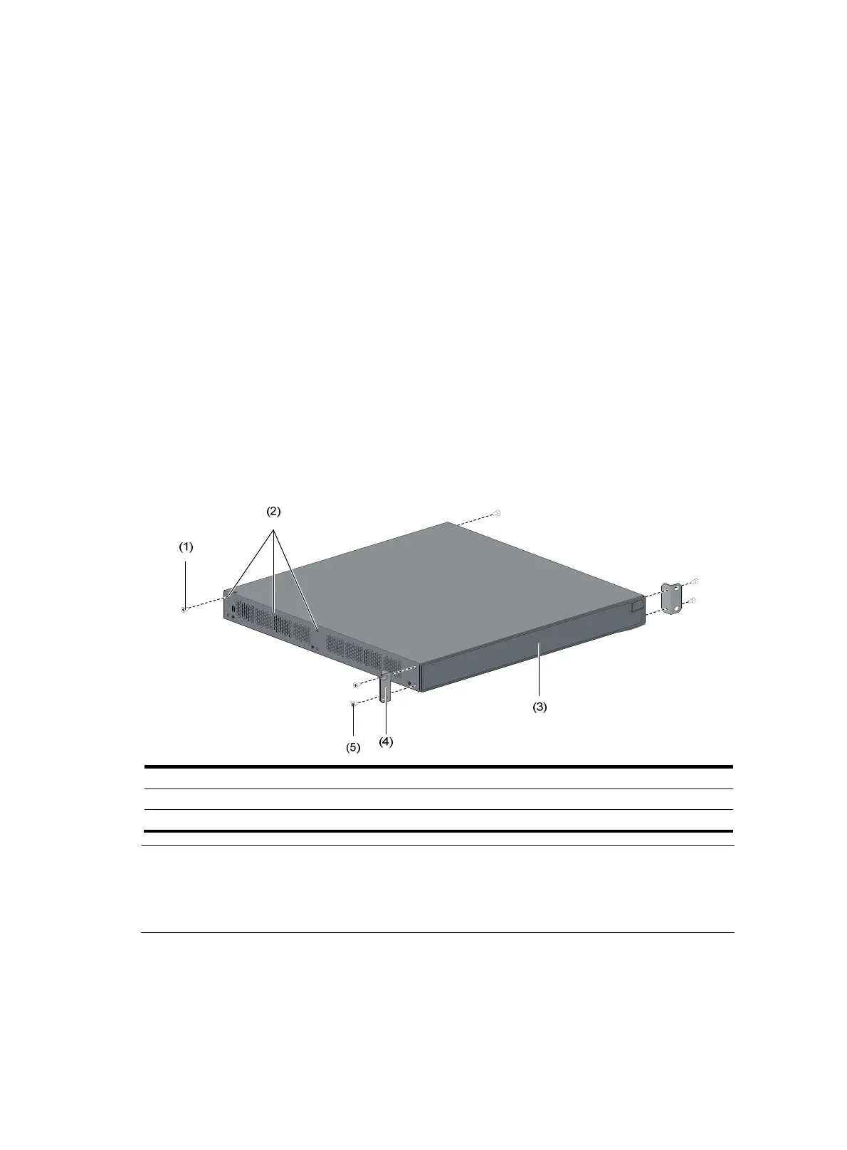
Figure 6 Attaching fro
nt mounting brackets and load-bearing screws
(1) Load-bearin
screw (2) Optional positions for load-bearin
screw
(3) Front panel (4) Front mountin
bracket
(5) Screw used to attach front mounting brackets to the switch
NOTE:
The switch provides three positions to mount a load-bearing screw on both sides. Select a proper
position accordin
to the actual requirements. The rear mountin
brackets ti
htly contacted with the
load-bearing screws can support the switch.
5. Select a position to install the switch and attach the rear mounting brackets to the rear posts with
screws and cage nuts, as shown in Figure 7.

 Loading...


