129
Similarly, Switch D is the default gateway of the hosts in segment 30.1.1.0/24. Two static routes to
20.1.1.0/24 exist on Switch D, with the next hop being Switch B and Switch C, respectively. These two
static routes back up each other as follows:
• The static route with Switch B as the next hop has a higher priority, and is the master route. If this
route is available, Switch D forwards packets to 20.1.1.0/24 through Switch B.
• The static route with Switch C as the next hop acts as the backup route.
• Configure static routing-track-NQA collaboration to determine whether the master route is available
in real time. If the master route is unavailable, the backup route takes effect, and Switch D forwards
packets to 20.1.1.0/24 through Switch C.
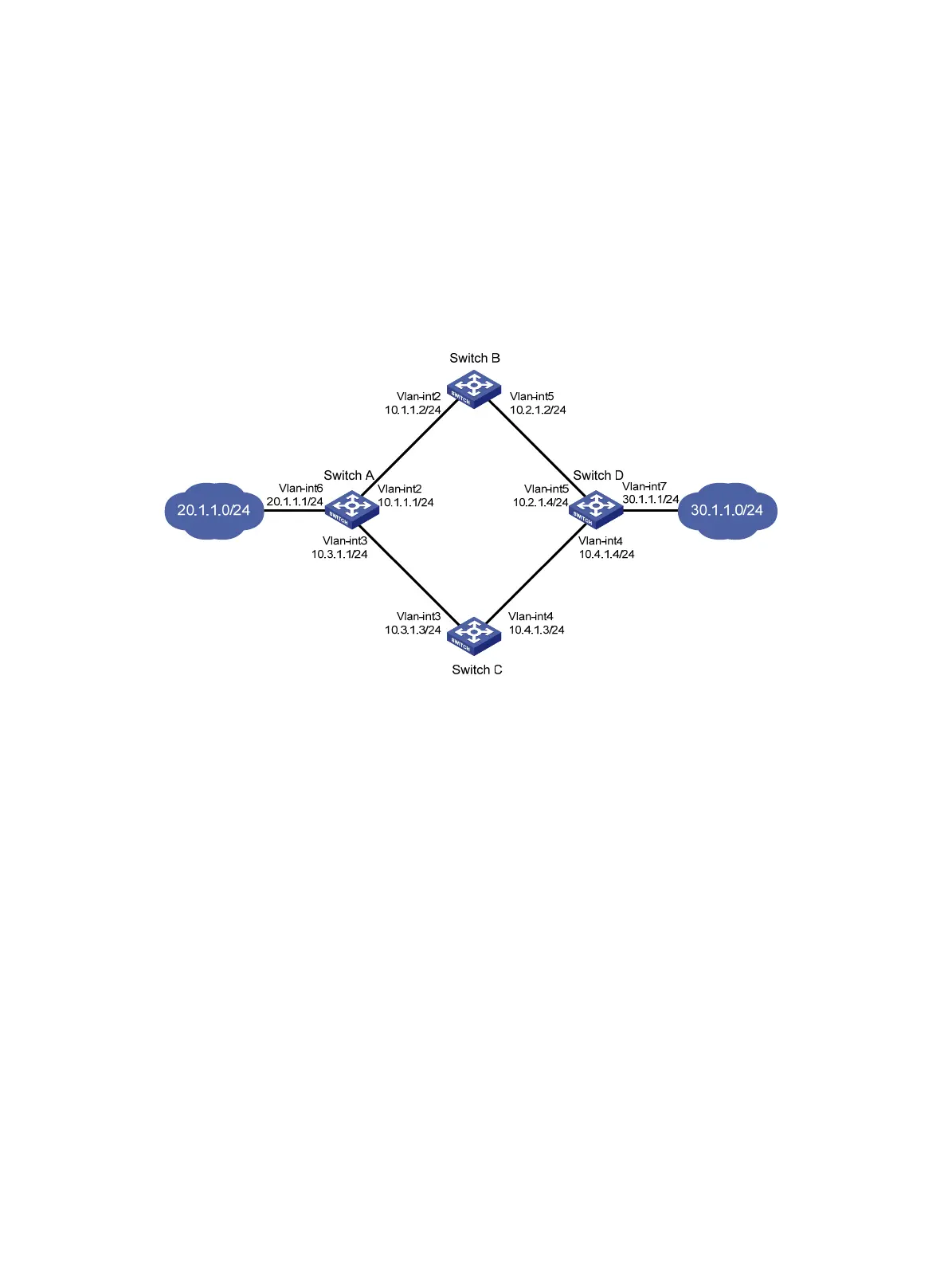
Figure 29 Network diagram
Configuration procedure
1. Create VLANs, and assign corresponding ports to the VLANs. Configure the IP address of each
VLAN interface as shown in Figure 29. (D
etails not shown.)
2. Configure Switch A:
# Configure a static route to 30.1.1.0/24, with the address of the next hop as 10.1.1.2 and the
default priority 60. This static route is associated with track entry 1.
<SwitchA> system-view
[SwitchA] ip route-static 30.1.1.0 24 10.1.1.2 track 1
# Configure a static route to 30.1.1.0/24, with the address of the next hop as 10.3.1.3 and the
priority 80.
[SwitchA] ip route-static 30.1.1.0 24 10.3.1.3 preference 80
# Configure a static route to 10.2.1.4, with the address of the next hop as 10.1.1.2.
[SwitchA] ip route-static 10.2.1.4 24 10.1.1.2
# Create an NQA test group with the administrator admin and the operation tag test.
[SwitchA] nqa entry admin test
# Configure the test type as ICMP-echo.
[SwitchA-nqa-admin-test] type icmp-echo
# Configure the destination address of the test as 10.2.1.4 and the next hop address as 10.1.1.2
to check the connectivity of the path from Switch A to Switch B and then to Switch D through NQA.

 Loading...


