11
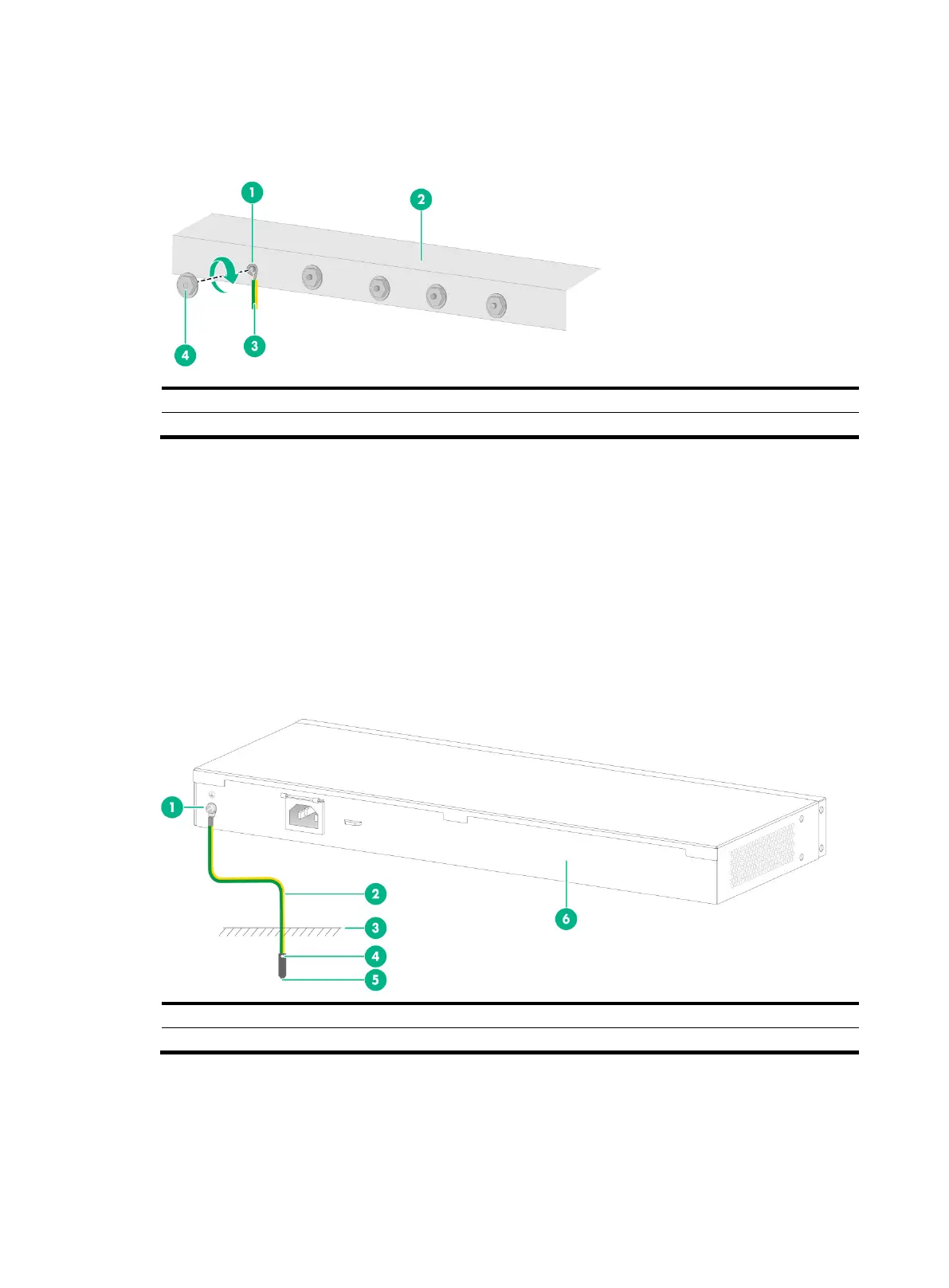
2. Attach the bended part of the grounding cable to the grounding post and use the hex nut to
fasten the bended part to the post.
Figure 14 Connecting the grounding cable to a grounding strip
Grounding the switch by using a grounding conductor buried
in the earth ground
If the installation site does not have grounding strips, but earth ground is available, hammer a 0.5 m
(1.64 ft) or longer angle iron or steel tube into the earth ground to act as a grounding conductor.
The dimensions of the angle iron must be a minimum of 50 × 50 × 5 mm (1.97 × 1.97 × 0.20 in). The
steel tube must be zinc-coated and its wall thickness must be at least 3.5 mm (0.14 in).
Weld the yellow-green grounding cable to the angel iron or steel tube and treat the joint for corrosion
protection.
Figure 15 Grounding the switch by burying the grounding conductor into the earth ground
Verifying the connection after grounding the switch
If you ground the switch by using a grounding strip, perform the following tasks:

 Loading...


