2-8
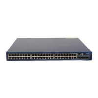
Figure2-4 Rear mounting bracket and shoulder screw
(1) Screw hole for attaching the bracket to the rack
Rack-mounting the switch
Attaching the front mounting brackets and shoulder screws to the switch
The switch provides two installation positions on its side for the front mounting brackets. One is near
the power supply side and one is near the port side. The following procedure attaches the front
mounting brackets to the installation position near the power supply side. The port-side mounting is
similar.
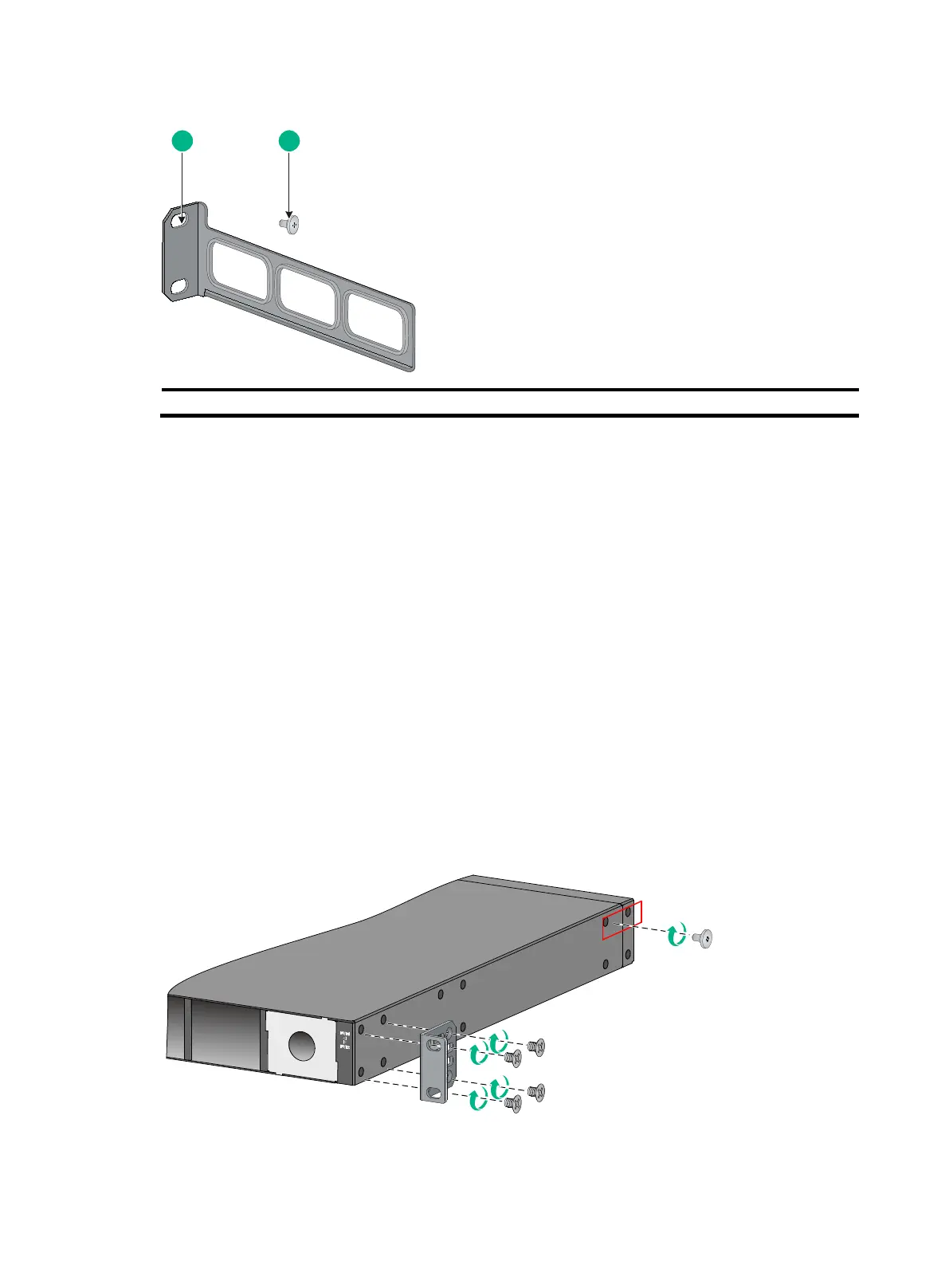
To attach the front mounting brackets and shoulder screws to the switch:
1. Wear an ESD wrist strap. Make sure the strap makes good skin contact and is reliably
grounded.
2. Align the round holes in the wide flange of one front mounting bracket with the screw holes in
the chassis. See Figure2-5.
3. Use M4 screws (supplied with the switch) to attach the mounting bracket to the chassis.
4. Repeat the preceding two steps to attach the other mounting bracket to the chassis.
5. Unpack the shoulder screws and attach them to the chassis.
Two installation positions as red-marked in Figure2-5 are available for shoulder screws. Select
one as required.
Figure2-5 Attaching the front mounting brackets and shoulder screws to the chassis

 Loading...