6
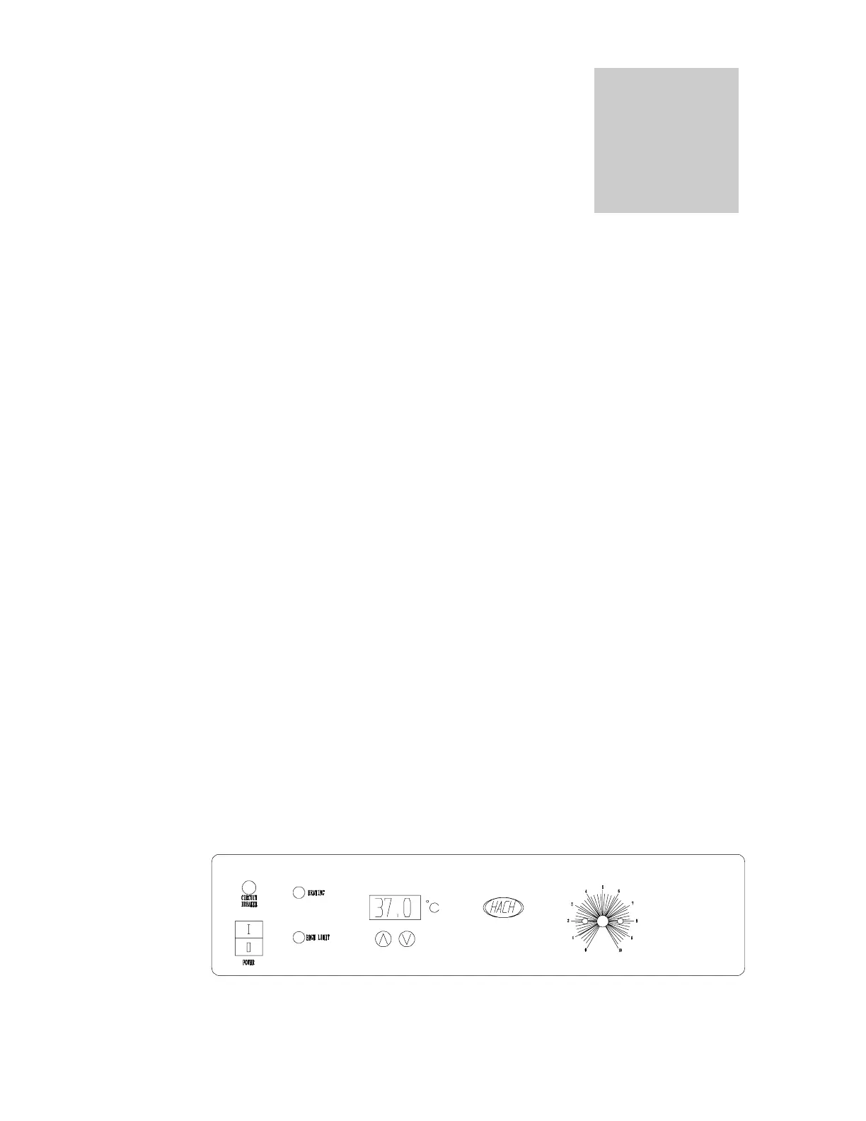
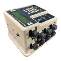
CONTROL PANEL OVERVIEW
( SEE FIGURE 1 )
3.1 Power Switch: The main power I/O (on/off) switch controls all power to
the unit and must be in the I/ON position before any systems are
operational.
3.2 Main Temperature Control: The Main Temperature Control consists of
the digital display and UP and DOWN arrow pads for inputting set point
temperatures and calibration.
3.3 HEATING Lamp: This pilot lamp is ON when the unit is heating up to set
point and is blinking when controlling temperature at set point.
3.4 High Limit Safety Thermostat: The manual dial marked from 0 to 10, the
High Limit Safety is a completely independent control that acts as an
override in the event that the Main control fails in the ON position. The
High Limit Safety will regulate chamber temperature at approximately 1°C
above the set point of the Main controller.
3.5 HIGH LIMIT Light: This pilot lamp comes ON when the High Limit
Thermostat is activated. Under normal operating conditions this light
should never be lit.
3.6 Circuit Breaker: The breaker can be manually reset by pushing in the
extended button when tripped. It offers protection against power source
variations. Protection is an addition to the automatic high-temperature limit
designed into the heating element and low limit control wired into the
cooling compressor.
Figure 1
(2 circuit breakers on 220V units)
Section