EasyManua.ls Logo

Hach SIGMA 900 User Manual

Hach SIGMA 900
94 pages
To Next Page IconTo Next Page
Page #1 background imageLoading...
Page #1 background image
Catalog Number 8837
Sigma 900 All Weather Refrigerated Sampler
USER MANUAL
March 2006, Edition 7
© Hach Company, 2002, 2003, 2006. All rights reserved. Printed in the U.S.A. eac/jk

Table of Contents

Other manuals for Hach SIGMA 900

Question and Answer IconNeed help?

Do you have a question about the Hach SIGMA 900 and is the answer not in the manual?

Hach SIGMA 900 Specifications

General IconGeneral
TypePortable Sampler
Power12 VDC
ControllerMicroprocessor-based
Pump TypePeristaltic
Operating Temperature0 to 50 °C (32 to 122 °F)
CommunicationRS-232
Storage Capacity24 bottles

Summary

Safety Precautions

Use of Hazard Information

Explains signal words (Danger, Caution, Note) for hazard communication.

Precautionary Labels

Details warning symbols and their meanings for safe operation.

Hazardous Locations

Confined Space Entry

Definition of Confined Space

Defines confined space and its hazardous conditions.

Product Specifications - General

General Specifications

Covers dimensions, weight, and cabinet details.

Sample Pump and Volume Specs

Details pump, sensor, volume, and repeatability specs.

Sampling Modes and Intervals

Lists sampling modes and interval settings.

Interface and Programming Features

Describes user interface, clock, programming features, language, and manual modes.

Product Specifications - Advanced Features

Multiple Programs, Cascade, and Data Logging

Details program storage, cascade, and data logging features.

Power, Environmental, and Cooling Specs

Lists power requirements, operating ranges, cooling, and temperature specs.

Section 1 Introduction

Instrument Description

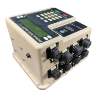
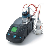
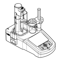
Provides an overview of the sampler's design and capabilities.

Principle Operation - Liquid Sensor

Explains how the liquid sensor enables accurate sample volumes.

Section 1 Introduction - Principle Operation Details

Principle Operation - Intake Rinse and Retry

Explains intake tube pre-rinsing and sample retry features.

Installation Safety and Warnings

Section 2 Installation - Site Selection and Sampler Mounting

Selecting the Installation Site

Guidelines for choosing location and mounting the sampler.

Installing the All Weather Refrigerated Sampler

Details steps for physically installing the sampler unit.

Section 2 Installation - Pump Tube Installation

Installing the Pump Tube in the Sensor Body

Explains how to install the pump tube correctly.

Section 2 Installation - Intake Line Connection

Attaching the Intake Line

Details how to connect the vinyl intake tubing.

Section 2 Installation - Teflon Tubing Assembly

Attaching the Teflon Tubing

Explains the assembly process for Teflon tubing.

Section 2 Installation - Setup and Power

Setting Up the Intake Line and Strainer

Guides on properly setting up the intake line and strainer.

Bottles and Retainers Installation

Instructions for installing sample bottles and retainers.

Power Connections and Safety

Provides instructions and safety precautions for power connections.

Section 2 Installation - Flow Proportional Operation

Contact Closure and Pulse Input

Details connecting to flow meters via contact closure and pulse inputs.

4-20 mA Input for Flow Proportional Sampling

Describes connecting to flow meters using 4-20 mA signals.

Section 2 Installation - Auxiliary Connections

Auxiliary Receptacle Functionality

Explains the auxiliary receptacle for I/O signals.

Section 3 Connecting to External Devices

Using 12V DC Connection

Details how to use the 12V DC connection for power.

Using the Auxiliary Connection

Explains the auxiliary connector and its pin assignments.

Section 3 Connecting to External Devices - Splitter Interface

Splitter Interface Usage

Describes the splitter interface for multiple connections.

Maintenance Safety and Warnings

Section 4 Maintenance - Cleaning Procedures

Cleaning the Sampler Components

Instructions for cleaning refrigerator, cabinet, and bottles.

Intake and Pump Tubing Cleaning

Procedure for cleaning intake and pump tubing.

Pump Tubing Maintenance Overview

Covers maintenance related to pump tubing.

Section 4 Maintenance - Pump Tubing Life

Tubing Life Estimates

Factors affecting pump tubing life and estimates.

Section 4 Maintenance - Component Care and Calibration

Replacing Pump Tubing

Step-by-step guide for replacing pump tubing.

Humidity Indicator and Desiccant Replacement

Explains humidity indicator and desiccant replacement.

Thermal Control System Calibration

How to calibrate the temperature control system.

Section 4 Maintenance - Fuse Replacement

Fuse Replacement Procedure

Instructions for replacing fuses.

Section 4 Maintenance - Circuit Breaker Reset

Resetting the Circuit Breaker

Steps to reset the internal circuit breaker.

Operation Safety Warnings

Section 5 Programming - Keypad and Basic Functions

Keypad and Key Functions

Explains the keypad layout and function of each key.

Section 5 Programming - Tips and Language Selection

Programming Tips and Techniques

Provides helpful tips for programming the sampler.

Selecting a Different Language

How to change the instrument's display language.

Section 5 Programming - Initial Setup

Using the Sampler for the First Time

Guides on initial setup and parameter entry.

Accessing Parameter Entry Mode

Steps to enter parameter entry mode.

Section 5 Programming - Program Messages (Part 1)

Explanations of Program Messages

Lists and explains various system messages shown on the display.

Section 5 Programming - Program Messages (Part 2)

Explanations of Program Messages

Continues listing and explaining system messages.

Section 5 Programming - Program Messages (Part 3)

Explanations of Program Messages

Continues listing and explaining system messages.

Section 5 Programming - Program Messages (Part 4) and Time/Date Setting

Explanations of Program Messages

Continues listing and explaining system messages.

Setting the Time and Date

Procedure for setting the sampler's internal clock and date.

Section 5 Programming - Program Management and Data Logging

Creating and Storing Multiple Programs

How to create, save, and retrieve multiple programs.

Data Logging Functionality

Explains how the sampler logs sample data.

Section 5 Programming - Manual Operation and Triggered Sampling

Manual Mode Operations

Guides on manual operation of pump and distributor arm.

Measurements Triggered by Levels or Flow

Explains sampling triggered by external conditions.

Section 5 Programming - Level Control and Storm Water Overview

Programming for Level Control

How to program sampling based on liquid levels.

Storm Water Programming Overview

Overview of storm water sampling capabilities.

Section 5 Programming - Storm Water Routine Programming

Programming Instructions for Storm Water Sampling Routine

Detailed steps for storm water programming.

Section 5 Programming - Special Outputs and Modes

Special Outputs Overview

Explains special output signals and their modes.

Section 5 Programming - Special Output Programming and Messages

Programming the Sampler for Special Outputs

Steps to program special output functions.

Special Output Messages

Explains messages related to special outputs.

Section 5 Programming - Advanced Program Features Overview

Advanced Program Features Overview

Introduces advanced programming features.

Section 5 Programming - Advanced Program Feature Details

Advanced Program Feature Details

Covers start/stop, intervals, and bottle configurations.

Section 5 Programming - Timed Bottle and Flow Proportional Operation

Timed Bottle Modes (Pre-Advanced)

Explains timed bottle modes and pre-advance functionality.

Flow Proportional Operation and Pulse Calculation

Details flow proportional setup and calculation methods for pulses.

Section 5 Programming - Flow Proportional Sampling Calculations

Calculating Intervals Using External Pulses

Calculating intervals using external pulses.

Section 5 Programming - 4-20 mA Flow Signal Calculations (Part 1)

4-20 mA Signal to Pulse Conversion Calculations

Calculating intervals using 4-20mA signals.

Section 5 Programming - 4-20 mA Flow Signal Calculations (Part 2)

4-20 mA Signal to Pulse Conversion Calculations

Continues calculation examples for 4-20mA signals.

Section 5 Programming - 4-20 mA Flow Signal Calculations (Part 3)

4-20 mA Signal to Pulse Conversion Calculations

Continues calculation examples for 4-20mA signals.

Section 6 Programming Worksheets - Main Program

Main Sampler Program Worksheet

Worksheet for configuring the main sampler program.

Section 6 Programming Worksheets - Main Program (Cont.)

Main Sampler Program Worksheet

Continuation of the main sampler program worksheet.

Section 6 Programming Worksheets - Volume Calibration

Volume Calibration Sheet

Worksheet for calibrating sample volume.

Section 6 Programming Worksheets - Storm Water Setup

Stormwater Setup Sheet

Worksheet for setting up storm water programming.

Section 6 Programming Worksheets - Storm Water Checklist

Stormwater Program Checklist

Checklist for storm water setup verification.

Section 6 Programming Worksheets - Final Check List

Final Check List

Final checklist before leaving the installation.

Appendix A Troubleshooting - Liquid Sensor Issues

Troubleshooting the Liquid Sensor

Diagnosing and resolving issues with the liquid sensor.

Appendix A Troubleshooting - Sampler Flow Chart (Part 1)

Troubleshooting Flow Chart

Flowchart for diagnosing and resolving sampler issues.

Appendix A Troubleshooting - Sampler Flow Chart (Part 2)

Troubleshooting Flow Chart, continued

Continuation of the troubleshooting flowchart.

Appendix B Quick Reference Guide - Programming Overview

Instrument Programming Overview

Overview of instrument programming steps and special functions.

Appendix B Quick Reference Guide - Programming Flow Charts (Part 1)

Programming Flow Chart

Visual guide for setting up various sampling programs.

Appendix B Quick Reference Guide - Programming Flow Charts (Part 2)

Programming Flow Chart, continued

Visual guide for setting up various sampling programs.

Appendix B Quick Reference Guide - Level Control/First Flush Flow Chart

Level Control/First Flush Flow Chart

Visual guide for level control and first flush sampling.

Appendix C Engineering Drawings - Assembly 1

Sampler Assembly Diagram (1 of 15)

Exploded view and parts list for assembly 1.

Appendix C Engineering Drawings - Assembly 2

Sampler Assembly Diagram (2 of 15)

Exploded view and parts list for assembly 2.

Appendix C Engineering Drawings - Assembly 3

Sampler Assembly Diagram (3 of 15)

Exploded view and parts list for assembly 3.

Appendix C Engineering Drawings - Assembly 4

Sampler Assembly Diagram (4 of 15)

Exploded view and parts list for assembly 4.

Appendix C Engineering Drawings - Assembly 5

Sampler Assembly Diagram (5 of 15)

Exploded view and parts list for assembly 5.

Appendix C Engineering Drawings - Assembly 6

Sampler Assembly Diagram (6 of 15)

Exploded view and parts list for assembly 6.

Appendix C Engineering Drawings - Assembly 7 (Wiring)

Sampler Wiring Diagram (7 of 15)

Wiring diagram and components for assembly 7.

Appendix C Engineering Drawings - Assembly 8

Sampler Assembly Diagram (8 of 15)

Exploded view and parts list for assembly 8.

Appendix C Engineering Drawings - Assembly 9

Sampler Assembly Diagram (9 of 15)

Exploded view and parts list for assembly 9.

Appendix C Engineering Drawings - Assembly 10

Sampler Assembly Diagram (10 of 15)

Exploded view and parts list for assembly 10.

Appendix C Engineering Drawings - Assembly 11

Sampler Assembly Diagram (11 of 15)

Exploded view and parts list for assembly 11.

Appendix C Engineering Drawings - Assembly 12

Sampler Assembly Diagram (12 of 15)

Exploded view and parts list for assembly 12.

Appendix C Engineering Drawings - Assembly 13

Sampler Assembly Diagram (13 of 15)

Exploded view and parts list for assembly 13.

Appendix C Engineering Drawings - Assembly 14

Sampler Assembly Diagram (14 of 15)

Exploded view and parts list for assembly 14.

Appendix C Engineering Drawings - Assembly 15

Sampler Assembly Diagram (15 of 15)

Exploded view and parts list for assembly 15.

General Information

Parts and Accessories

Contact Information for U.S.A. and Outside Europe

Contact Information for Europe

Warranty Information

Related product manuals