Section 2
Page 21
8837hrd.fm Flow Proportional Operation
multimeter, with an appropriate range to measure 1 to 5 V dc. With transmitter
on, and the 4–20 mA interface wired into the series loop, attach the (+) test
probe to the wire with clear insulation and the common (-) test probe to the
wire with black insulation. The multimeter should indicate a positive
1 to 5 V dc reading on the scale. If the reading indicates a negative voltage,
the interface wires should be reversed, and the polarity checked on all other
receivers in the series loop.
For details on programming the sampler for flow proportional operation, refer
to section 5.15 on page 50.
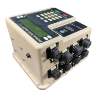
Figure 6 Interface for 4–20mA and Pulse Duration Input
2.7.4 Auxiliary Receptacle
The Auxiliary interface connector is a general purpose input/output port. Refer
to on page 23 for a detailed description of the auxiliary receptacle
connections. Section 5 on page 35 explains how to configure the sampler
program for the Auxiliary signals.
To Auxillary Connector
(-)
(+)

 Loading...