Figure 11 shows the alarm relay contacts connected to the terminal strip with normally open and
normally closed terminations. Terminals are unpowered and rated for 5 A at 100–240 VAC resistive
load.
The relay connector accepts 18–12 AWG (0.75–1.0 mm
2
) wire. Select the necessary wire gage that
operates with the application. A wire gauge less than 18 AWG (0.75 mm
2
) is not recommended.
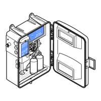
Figure 11 Alarm connections
Table 2 Relay wiring
Terminal block Terminal 1 Terminal 2 Terminal 3
J7 COM Normally open (NO) Normally closed (NC)
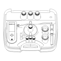
3.4 Install the buffer solution
Buffer solutions are formulated at the factory and are ready to install without preparation. Put the
bottle in the instrument as shown in Figure 12 on page 16. Refer to Buffer and indicator solution for
the applicable trip point on page 24.
3.5 Install the indicator solution
Indicator solutions are formulated at the factory and are ready to install without preparation. Put the
bottle in the instrument as shown in Figure 12. Refer to Buffer and indicator solution for the
applicable trip point on page 24.
English
15