SETTINGS AND AJUSTEMENTS
WARNING! During seƫngs and adjustments ensure the drill press
is disconnected from the power supply.
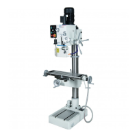
TABLE HEIGHT ADJUSTMENT
1. Loosen the table support lock (Fig. 22).
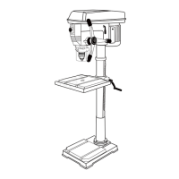
2. Rotate the table adjustment handle to
set the desired table height and ghten
the table rock to secure the table in
posion (Fig. 23).
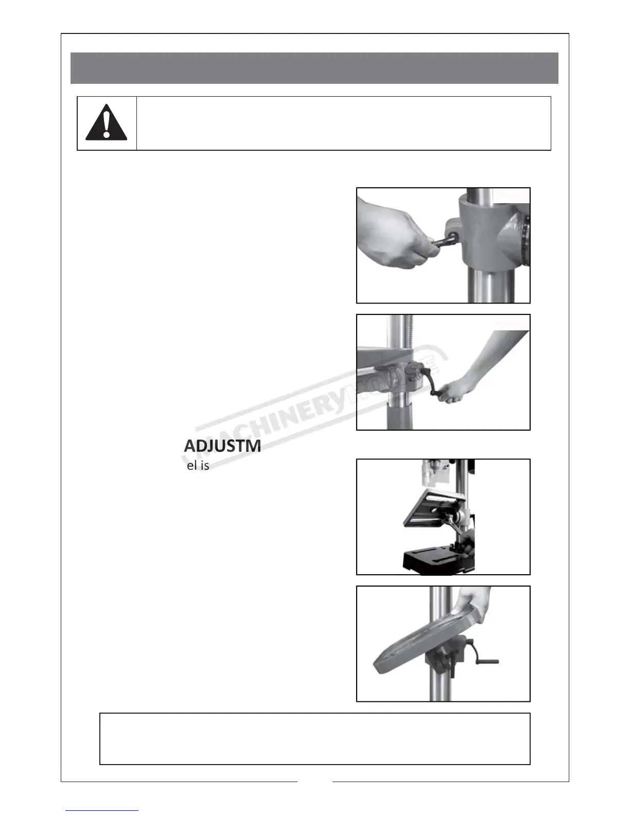
TABEL BEVEL ADJUSTMENT
1. The bevel angel is adjusted by loosening
the bolt that is located underneath
table support with a spanner (Fig. 24).
12
2. Aer lng the working table (Fig. 25)
to appropriate posion, re-ghten the
bolt to secure its posion.
CAUTION: When the table is angled/tilted, ensure the workpiece
is clamped to the table.
Fig.22
Fig.23
Fig.24
Fig.25
 Loading...