SERVICE MANUAL
Model: AFL631 & CFE633
27
Issue 200905
Rev. Ref0905S003V0
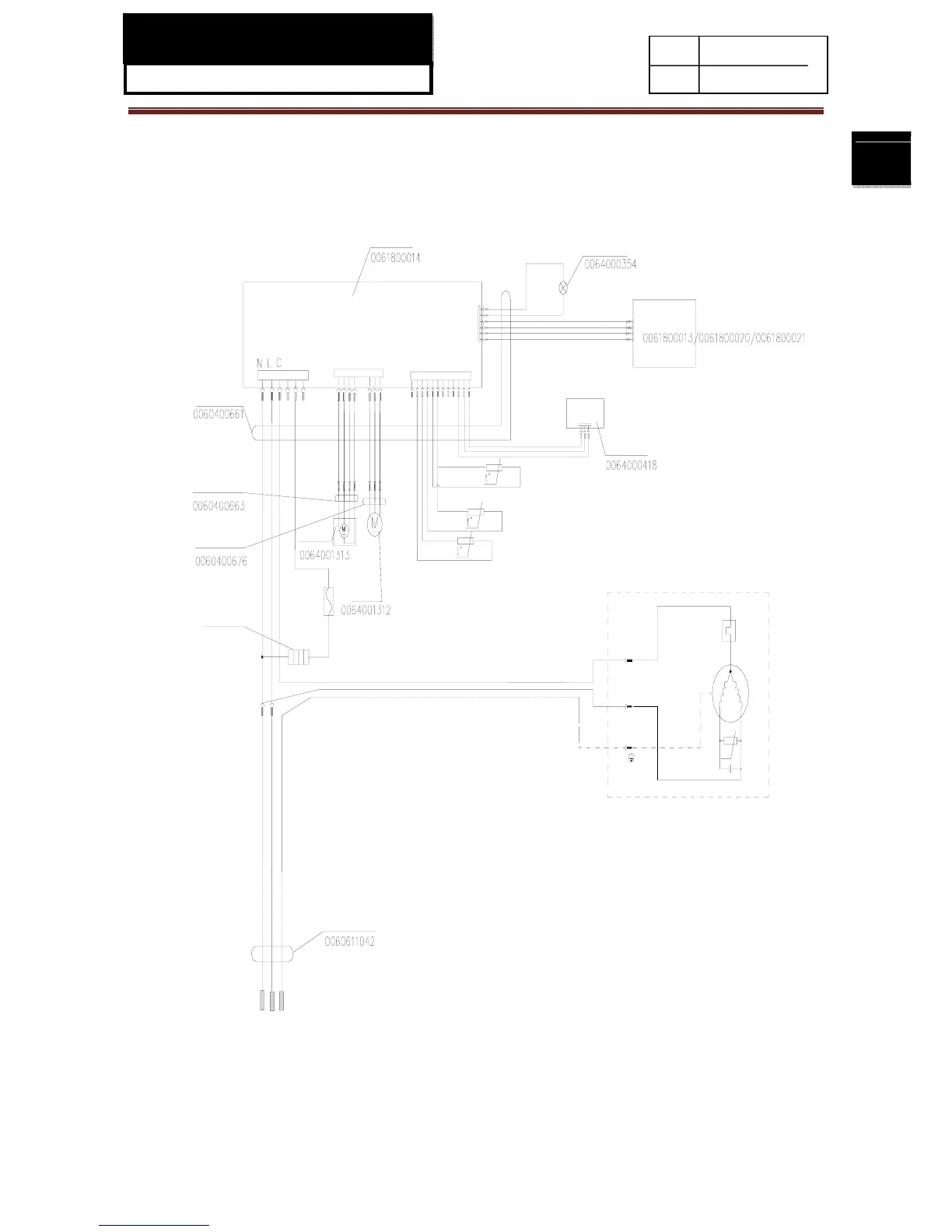
Chapter 7 Circuit diagram
7-1. Main control PCB diagram
6
1
1
6
10
1
12
1
CON4
CON3
CON2
CON1
Air escaper connecting cable
Fan motor connecting cable
Electric air escaper
Freezer storage temperature sensor
Defrosting temperature sensor
Fridge storage temperature sensor
Heating tube
0064000353
C
N
P
θ
S
R
HT
Power board
LED Lamp
Main control cable
Display panel
Switch
Power cable
Fan motor
Fuse
Yellow/Green
Blue
Brown
Yellow/Green
Blue
Black
Blue
Brown
Black
Red
 Loading...