110
Smart Power
1UH125&140P1ERK
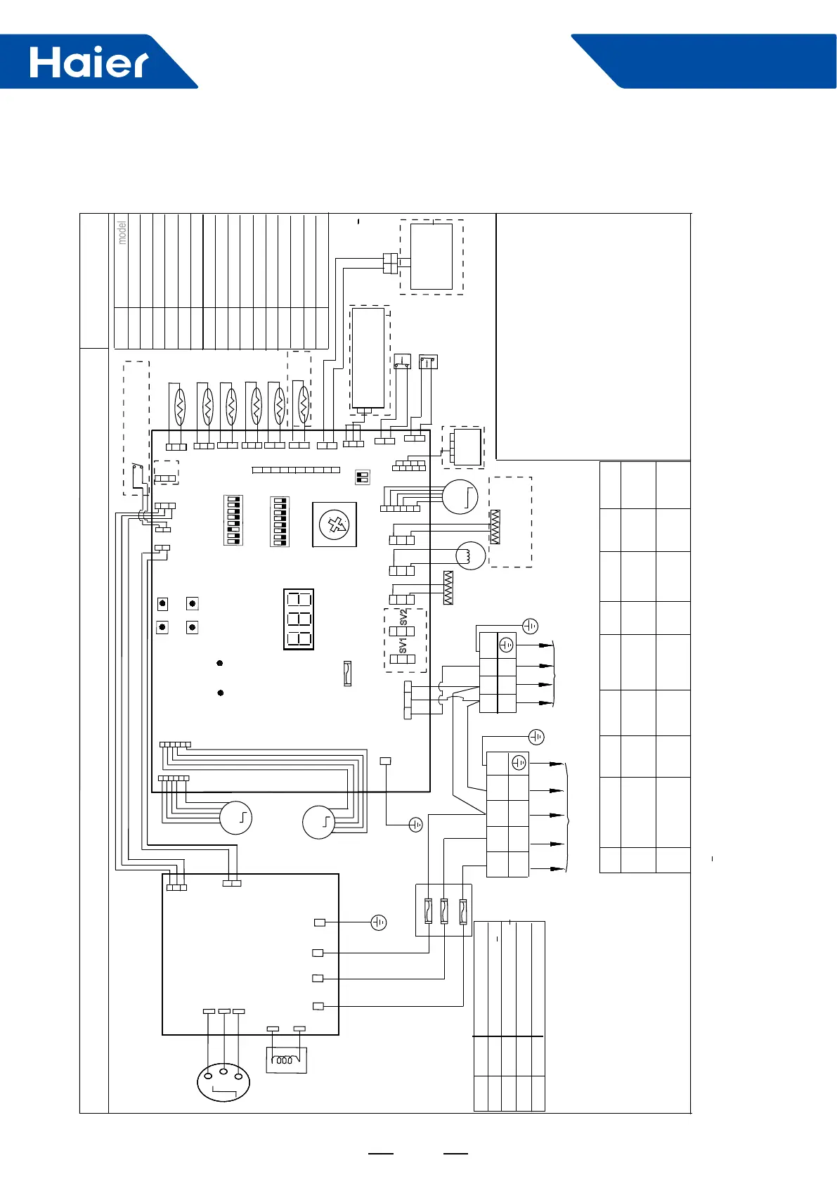
CIRCUIT DIAGRAM OF OUTDOOR UNIT
0
1
2
3
SW 8
Definition
(
model
)
1UH090N1ERG
1UH105N1ERG
4
5
6
7
8
9
A
B
C
D
E
F
1UH125P1ERG
Reserved
Reserved
Reserved
Reserved
Reserved
Reserved
T
1
2
POWER SUPPLY
TO INDOOR UNIT
Y/G
3
N
BLU
BLK
W
U
CO
M
P
RES
SOR
V
U
V
W
DRIVER
MODULE
CN605
FILTER&
Y/G
1UH071N1ERG
L
E
D
1
L
ED
2
power
indicate
communication
indicate
T6.3A/250VAC
F
USE1
CN
2
DRED
CN
1
CN
14
CN10
CN23
CN
21
CN
5
CN
3
CN
4
C
N6
CN
7
CN24
CN
8
CN
18
CN13
CN12
M
M
L
E
D
3
error&status indiate
O
N
SW6
O
N
4321
8765
CONT
ROL
B
O
A
R
D
0
F
E
D
C
B
A
9
8
7
6
5
4
3
2
1
S
W
8
S
W2
S
W3
S
W5
S
W4
MODE
UP
SET
DOWN
BLK
L
NSIG
M
E.E.V
CN19
SV1
CN17
SV2
CN20
CN16
CN9
RD
WHT
BLK
12V
GND
CN25
PWD
module
com1
C
N
15
C
N
11
module
com2
CN22
Crankcase
heater
(CHTR)
4WV
Tcm
Td
Te
Ta
TS
TH
Reserved
1UH140P1ERG
Reserved
Reserved
1UH140P1ERK
1UH125P1ERK
SW7
O
N
21
SW1-1
SW1-2
SW1-3
SW1-4
SW1-5
SW1-6
SW1-7
SW1-8
ON
OFF
Manually
forced operation
Valid
Manually
forced operation
invalid
Manually
forced
cooling
Manually
forced
heating
low stand
by power
cost
normal
stand by
cost
unit as
air conditi-
oner
Refrigerant
R410A
Defrost
automatic
Defrost
by time
Not for
base
station
GND
S
CN624
5V
WHT
BLK
RD
WHT
GROUND
CN608
CN603
CN602
0150516954
Y/G
SR
T
S
CN601
R
L2
L1
REACTOR
RD
DC F
AN MOT
OR 1
DC F
AN MOT
OR 2
( UPPER MOTOR )
( LOWER MOTOR)
central
control
***************************************************************
Tcm:Temperature sensor of condenser’s middle position
Ts:Compressor suction temperature sensor
Te: Defrost tempreature sensor
Tao:Outdoor unit ambient temperature sensor
Td:Compressor dischargetemperature sensor
Th:Temperature sensor of hot water(optional)
E.E.V:Electronic expansion valve
LP:Low pressure switch
HP:High pressure switch
DERD:Demand response enabling device
(Only used in
Australia and New Zealand area
)
***************************************************************
BLK:black WHT:white RD:red Y/G:yellow/green
Explanation of abbreviations 1:
BLU:blue
4WV:Four way valve
BMS:Building Management System
2.SW6 is used for central control adress selection
refer to service manual to get more details
3.Once out of factory ,do not change the switches
of SW1,SW6,SW7,SW8 without technical guidence.
4.Can do the parameters checking work by button
switches SW2/SW3/SW4/SW5 and digital display
LED 3,refer to service manual to get more details.
5.For maintenance safety ,please operate after pow-
er supply cut off at least 3 minutes
CON1
Y/G
LP
HP
A
B
C1 C2
RD
BRN
BRN:brown
SW1
4321
8765
NOTE:
SW7-1
OFF
OFF
OFF
ON
ON
OFF
ON
ON
SW7-2
Definition
DERD test selcetion 0
DERD test selcetion 1
DERD test selcetion 2
DERD non-test selcetion
25A/500VAC
25A/500VAC
25A/500VAC
BLK
WHT
RD
FUSE BOARD
④Bottom heater
(BHTR)
⑥ water he-
ater or hea-
ting only
③
BMS
⑤Refriger
ant R32
⑦Base
station
application
CENTRAL
CONTROLLER
/③BMS DEVICE
Parameters monitor
adaptor /②
Hydro unit
①external dry contact
input(
ON/OFF signal)
1.Dashed parts are optional.marks①②③④
⑤⑥⑦are function in future.
 Loading...