156
Smart Power
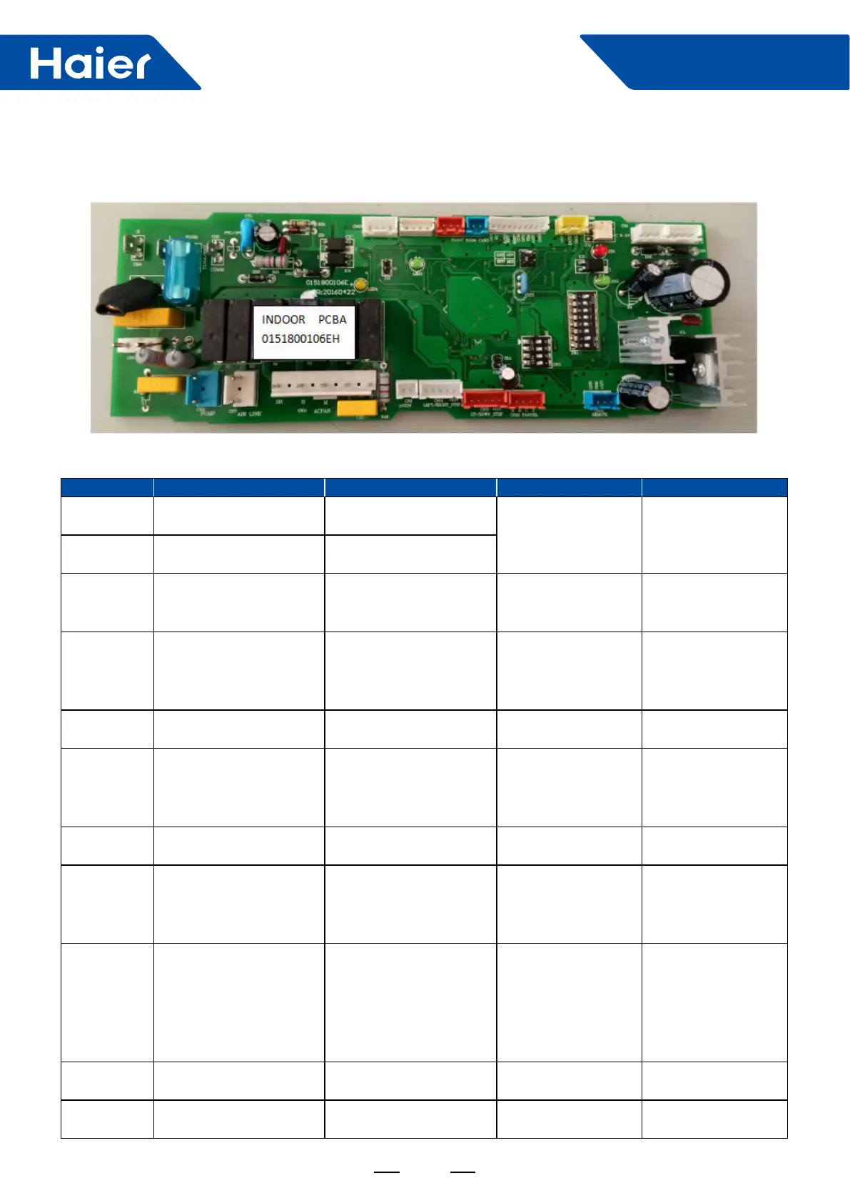
Connector Description Connected to Port function Remark
CH3 L
Indoor terminal block
terminal label 2
PCB AC power supply 220-240VAC input
CH4 N
Indoor terminal
blockterminal label 1
CH5
COMM (communication
port)
Indoor terminal block
terminal label 3
Communication port
for indoor unit and
outdoor unit
CN1
Wired controller port
(C,B,A)
Wired controller
Wired controller power
supply and
wired controller
communication
I.D. PCB A,B,C
corresponding to
wired controller A,B,C
in sequence
CN3
TRANS2(Transformer
secondary side)
Transformer secondary
side connector
Transformer
secondary side output
two group of DC 12V
into CN3
CN4 WIFI WIFI MODULE
Wi module power
supply and
wi module
communication
CN5
TRANS1(Transformer
primary side)
Transformer primary
side connector
Transformer primary
side input
CN6 DC FAN COMM
Fan motor driver board's
CN1
Communication port
for indoor main control
PCB and fan motor
driver board
5V,DATA,GND
corresponding to
5V,DATA,GND in
sequence
CN7 AIR LINK/E.A.O
Relay which for fresh air
motor/AC external alarm
Output E.A.O)
AC output for fresh air
motor/AC output when
error occurs
1.contact rating-230
VAC,3A)
2.E.A.O valid only
when SW1-6&SW1-
7&SW1-8 has been
set to ON ON OFF
CN8 ANION Relay for heater DC 12V for relay
get realy from local
market
CN9 PUMP Pump motorconnector
AC output for pump
motor
220-240VAC output
The PCB connectors description as following table:
 Loading...