4. Operation
(cont'd)
4-3. Operation
CAUTION
●
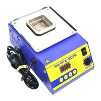
Keep the solder pot cover closed until the solder is fully melted.
●
The solder pot cover is very hot. Do not touch anything other than the front section of the frame.
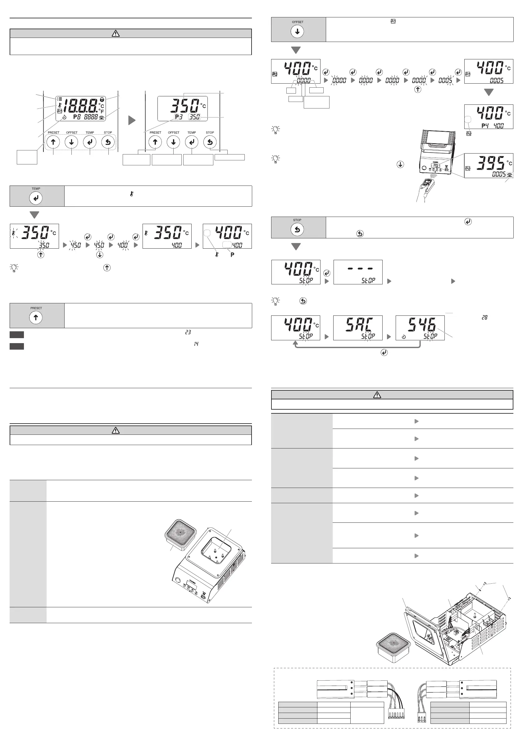
(1)
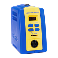
Turn the power on.
(2)
Below shows what is displayed.
(3)
Once the set temperature is reached, open the solder pot cover when ready to use.
(4)
Keep the solder pot cover closed when not in use.
Lock icon
Temperature
icon
Offset icon
Timer icon
Communication Communication
iconicon
Setting
temperature
Temperature
Correction mode
Temperature
Setting Mode
Preset icon
Pot sensor
temperature
Parameter
icon
Up
button
Down
button
Confirm
button
Back
button
Stop Mode
Operation
button
Preset No.
Mode
■
Changing the temperature setting
Push
Push this button once to display [ ] and transition to "temperature setting mode."
This mode is used when changing the set temperature.
Push once
[
] and [ ]
disappear.
Temperature
control begins
Normal screen
To change to 400ºC
Push five times
Push Push Push
Once the normal screen appears, push the button to transition to preset No. mode.
■
Changing the preset No.
You can register up to ve frequently used setting temperatures on the product, and then select the
registration No. to change the setting temperature.
Push
Push this button once to transition to "preset No. mode."
Select one of the ve temperatures registered in this mode.
( Factory default temperature settings: P1 250ºC (600ºF), P2 300ºC (700ºF), P3 350ºC (750ºF),
P4 400ºC (800ºF), P5 450ºC (850ºF))
NOTE
The registered temperature of each preset No. can be changed in "parameter No.
."
(See the separate document "Quick Parameter Settings")
NOTE
If you want to limit setting temperature changes, change the setting in "parameter No.
."
(See the separate document "Quick Parameter Settings")
■
Internal pot temperature correction (oset)
Push
Push this button once to display [ ] and transition to "temperature correction mode." If the
setting temperature and measured value of the internal pot temperature dier in this mode, you
can correct the temperature.
(Correction range: ±100ºC/±180ºF)
Push five times
[
] disappears.
Normal screen
To correct a temperature by 5ºC for a setting of 400ºC
(to correct actual internal pot temperature reading 395ºC when set to 400ºC)
0 to 9
(ºF: 0 to 8)
–/0
* Note that temperatures that exceed the correction range cannot be entered.
0 to 9
0 to 1
Temperature sending screen
The internal pot temperature can change if it contains too many
impurities. The internal pot temperature changes if you replace the
pot, so the oset will need to be readjusted. Make sure to change
the oset value as needed while monitoring the actual internal pot
temperature.
You can automatically change the oset value using a HAKKO
thermometer with a temperature sending function. Push the
button before sending the measured value. (See the gure on the
right)
The communication icon is
only displayed at this state.
Push Push Push Push Push Push
Temperature
control begins
■
Checking the drop in temperature inside the pot (Stop mode: Heating element o)
Push
Push this button once to display the conrmation screen, then push the button to conrm.
This will turn o the heating elements and is used to show the pot temperature cooling to a safe
level. Push the
button again to turn the heaters on and return to normal operation.
Confirmation screen Dropped to room temperature
Turn o the power. Replace the pot.
Push
Push the button once to check the "solder type" and "accumulated pot usage time" set in the parameters.
(See the separate document "Quick Parameter Settings")
Setting temperature Solder type Accumulated pot usage time
This is displayed if you select [ON]
in Parameter No.
.
Use this to estimate the pot
replacement schedule.
5,460 hours
(546 × 10 hours = 5,460)
Loops for one minute until you push the button.
5. Parameter Settings
You can change the parameter settings to suit dierent work environments. See the separate document
"Quick Parameter Settings."
6. Maintenance
CAUTION
Use with caution, this product get hot during use.
Conducting maintenance will help keep the product in good condition and prolong the usage of the unit.
■
Daily maintenance
Wear and tear on the pot will vary due to the operating temperature as well as the quality and amount of
solder used. Maintenance should be performed based on what suits your usage.
Setting
temperature
Using the product at a temperature that is higher than necessary can accelerate pot
deterioration and damage parts that are susceptible to heat. Use lowest temperature
whenever possible.
Before
beginning
work
●
Pot
When cool, remove the pot and visually check the following:
・
Are there any holes in the pot?
・
Has any solder leaked onto the heat
insulation plate?
・
Has any foreign matter collected on the heat
insulation plate?
Make sure to change the orientation of the pot
each time you remove it. Doing so can slow
pot deterioration.
●
Solder pot cover
Remove any solder stuck to the cover. Doing
so can prevent any solder from unintentionally
falling into the pot. Make sure to do so when
changing the solder type.
When pausing
work
Turn o the unit for long periods of unused time.
●
Solder
Remove any oxidation or foreign matter in the molten solder using the spatula.
7. Troubleshooting
CAUTION
Before performing an inspection or replacing parts, make sure to disconnect the power plug from the outlet.
No operation even if
power switch is turned
ON.
Is the power cord connected?
Connect the power cord to the main
unit.
Is the fuse blown?
Replace the fuse.
If the fuse is blown again, send the
main unit back for service.
[L - E] is displayed.
Is there any foreign matter on
the heat insulation plate located
under the pot?
Remove/clean any foreign matter.
Is there any holes in the pot and
has solder leaked into the interior
of the main unit?
Remove the solder and replace the pot.
[S - E] is displayed.
Is the heating element connected
to the board?
Connect it to the board.
The internal pot
temperature is too high/
low.
Is the oset value entered
correct?
Measure and adjust the value.
(See "
■
Internal pot temperature
correction (oset)" in "4-3. Operation")
Is one of the heating elements
burnt out?
If the resistance of the heating element
is abnormal, replace it.
(See "How to check the heating element
resistance")
Is the heating element connected
to the board?
Connect it to the board.
If you cannot nd a solution in this manual, or if another problem occurs, please contact the retailer
where you purchased the product.
How to check the heating element resistance
(1)
Disconnect the power plug from the outlet.
(2)
Remove the pot when it is cool.
(3)
Remove the screws and washer securing the cover.
(4)
Open the cover.
(5)
Disconnect the heating element connector from
the board.
(6)
Measure the resistance of the heating element
when it is at room temperature.
(See below for pin layout and resistance
references)
(7)
Replace the heating element if the value is
abnormal.
Pot
Heat insulation plate
1 3
1 3 56
Heating element
right side
Heating element
left side
Between pins 1 - 3 Between pins 5 - 6
100 V / 110 V 8 to 13 Ω
129 to 191 Ω120 V 13 to 18 Ω
220 V / 230 V / 240 V 46 to 63 Ω
Normal resistance for
heating element left side
(at room temperature)
Normal resistance for
heating element right side
(at room temperature)
Between pins 1 - 3
100 V / 110 V 5 to 9 Ω
120 V 9 to 12 Ω
220 V / 230 V / 240 V 31 to 42 Ω
Cover
Washer
Screw
 Loading...