®
High-output, temperature controlled
soldering station
Instruction Manual
●
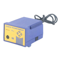
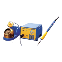
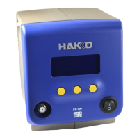
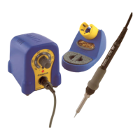
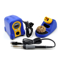
Thank you for purchasing the FP-101 soldering station. This
high-output, temperature controlled soldering station uses a
composite tip, incorporating heater and sensor functions into
one element. Several process control features unique to the
FP-101 make it applicable to a broad range of soldering
applications.
Please read this manual before operating the FP-101. Keep
this manual readily accessible for reference.
●
TABLE OF CONTENTS
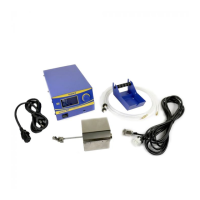
1. PACKING LIST ............................................................... 1
2. SPECIFICATIONS .......................................................... 1
3. WARNINGS, CAUTIONS, NOTES AND EXAMPLES ..... 2
4. PART NAMES ................................................................. 3
5. INITIAL SETUP .............................................................. 3
6. OPERATION ................................................................... 5
7. PARAMETER SETTINGS ............................................... 6
8. MAINTENANCE ............................................................. 7
9. ERROR MESSAGES ...................................................... 9
10. TROUBLE SHOOTING GUIDE .................................... 10
11. PARTS LIST .................................................................. 11
12. TIP STYLES ................................................................. 13
13. WIRING DIAGRAM ....................................................... 15