●
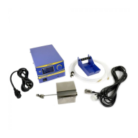
Thank you for purchasing the HAKKO FU-500 solder feed unit.
Please read this manual before operating the HAKKO FU-500.
Keep this manual readily accessible for reference.
●
TABLE OF CONTENTS
......................................................... 1
................................................. 1
................. 2
........................................................ 3
...................................................... 5
............................................................7
.....................................................18
...........................................19
................................21
................................................ 22
......................................................... 23
1. PACKING LIST
2. SPECIFICATIONS
3. WARNINGS, CAUTIONS AND NOTES
4. PART NAMES
5. INITIAL SETUP
6. OPERATION
7. MAINTENANCE
8. ERROR MESSAGES
9. TROUBLE SHOOTING GUIDE
10. EXPLODED VIEW
11. PARTS LIST
2018.1
MA02899XZ180131
Solder feed unit
11. PARTS LIST
For more information about replacement parts or latest information , please visit
our website (http://www.hakko.com) or HAKKO Document Portal. (see below)
Instruction Manual
© 2017-2018 HAKKO Corporation. All Rights Reserved.
OVERSEAS AFFILIATES
U.S.A.: AMERICAN HAKKO PRODUCTS, INC.
TEL: (661) 294-0090 FAX: (661) 294-0096
Toll Free (800)88-HAKKO
4 2 5 5 6
http://www.hakkousa.com
HONG KONG: HAKKO DEVELOPMENT CO., LTD.
TEL: 2811-5588 FAX: 2590-0217
http://www.hakko.com.hk
E-mail:info@hakko.com.hk
SINGAPORE: HAKKO PRODUCTS PTE., LTD.
TEL: 6748-2277 FAX: 6744-0033
http://www.hakko.com.sg
E-mail:sales@hakko.com.sg
Please access to the following address for the other Sales affiliates.
http://www.hakko.com
HEAD OFFICE
4-5, Shiokusa 2-chome, Naniwa-ku, Osaka 556-0024 JAPAN
TEL:+81-6-6561-3225 FAX:+81-6-6561-8466
http://www.hakko.com E-mail:sales@hakko.com
23
Part No.
BX1000
BX1001
BX1002
BX1003
BX1004
BX1005
BX1006
Part No.
BX1007
BX1008
BX1009
Part No.
BX1010
BX1011
BX1012
BX1013
BX1014
BX1015
Part No.
BX1018
BX1019
BX1020
BX1021
BX1022
BX1057
BX1036
BX1037
Part Name
Solder feed pulley unit / 0.3 mm
Solder feed pulley unit / 0.5 mm
Solder feed pulley unit / 0.6 mm
Solder feed pulley unit / 0.8 mm
Solder feed pulley unit / 1.0 mm
Solder feed pulley unit / 1.2 mm
Solder feed pulley unit / 1.6 mm
Part Name
Solder feed guide set / 0.3 mm
Solder feed guide set / 0.5 - 1.0 mm
Solder feed guide set / 1.2 - 1.6 mm
Part No.
BX1041
BX1042
Part No.
CX1010
CX5006
Part Name
Tube unit / 0.3 - 1.0 mm
Tube unit / 1.2 - 1.6 mm
Part name
Feeder unit / 0.3 - 1.6 mm
Feeder unit / 0.3 - 1.6 mm
Specifications
Specifications
Specifications
Specifications
Type L
Type straight
Specifications
set of 10
Specifications
Withferrite
core
Part Name
Teflon tube / 0.3 mm
Teflon tube/ 0.5 - 0.6 mm
Teflon tube/ 0.8 mm
Teflon tube / 1.0 mm
Teflon tube / 1.2 mm
Teflon tube / 1.6 mm
Part Name
Guide tube
Guide pipe / 0.3 mm
Guide pipe / 0.5 - 1.0 mm
Guide pipe/ 1.2 - 1.6 mm
Grommet
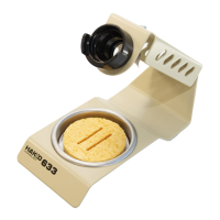
Solder reel stand
Feeder cable / 5 m
Feeder cable / 8 m
Feeder unit
Type L Type straight
Feeder cable
Grommet
Tube unit
Teflon tube
Guide tube
Guide pipe
Solder feed
guide set
Solder feed pulley unit
Solder reel stand
FU-500