EasyManua.ls Logo

Hakko Electronics FM-202 User Manual

Hakko Electronics FM-202
26 pages
To Next Page IconTo Next Page
Page #1 background imageLoading...
Page #1 background image
rxic
^HAK<^
SOLDERINO
STUTION
MODEL
FM-202
High-output,
temperature
controlled
soidering
station
Instruction
Manual
Thank
you
for
purchasing
the
FM-202
soldering
station.
This
high-output,
temperature
controlled
soldering
station
uses
a
composite
tip,
incorporating
heater
and
sensor
functions
into
one
element.
Several
process
Control
features,
unique
to
the
FM-202,
make
it
applicable
to
a
broad
range
of
soldering
ap-
plications.
Piease
read
this
manual
before
operating
the
FM-202.
Keep
this
manual
readily
accessible
for
reference.
TABLE
OF
CONTENTS
1.
PACKING
LIST.1
.2.
SPECIFICATIONS.1
3.
WARNINGS,
CAUTIONS,
NOTES
AND
EXAMPLES.2
4.
PART
N
AM
ES.3
5.
INITIAL
SETUP.3
6.
OPERATION.5
7.
TIP
IDENTIFICATION
NUMBER.9
8.
PARAMETER
SETTINGS.10
9.
MAINTENANCE.12
10.
ERROR
MESSAGES.14
11.
TROUBLE
SHOOTING
GUIDE.15
12.
PARTS
LIST.17
13.
TIPSTYLES
.20
14.
APPENDIXA.22
15.
WIRING
DIAGRAM.23
Question and Answer IconNeed help?

Do you have a question about the Hakko Electronics FM-202 and is the answer not in the manual?

Hakko Electronics FM-202 Specifications

General IconGeneral
TypeSoldering Station
Temperature ControlDigital
Heating ElementCeramic
Temperature Stability±1 °C
Tip to Ground Potential< 2 mV
Standby ModeYes
Tip to Ground Resistance<2 ohms
Weight1.2 kg
Tip ReplacementTool-free
Power Consumption70W
Voltage24V
Temperature Range200°C to 480°C (392°F to 896°F)

Summary

Specifications

FM-202 Soldering Station Specs

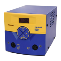
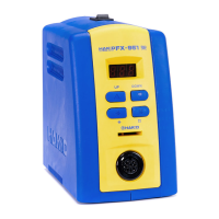
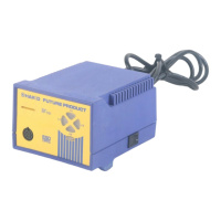
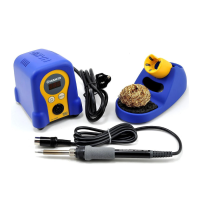
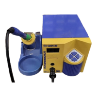
Detailed specifications for the FM-202 soldering station unit.

Station Unit Specifications

Technical details regarding the station's output, dimensions, and weight.

Soldering Iron Specifications

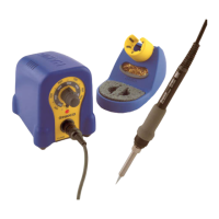
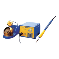
Technical details regarding the soldering iron's power, resistance, and length.

Safety Warnings and Cautions

Operational Cautions and Guidelines

Important safety warnings and operational cautions to prevent injury and damage.

Initial Setup Procedures

Operating the FM-202

Changing Temperature Settings

Step-by-step guide to adjust the soldering station's temperature using the control card.

Tip Identification and Entry

Entering Tip ID Data

Explains how to electronically compensate for tip geometry variations using Tip IDs.

Parameter Settings Configuration

Maintenance Procedures

Error Messages and Codes

Sensor Error (S-E)

Indicates a failure in the sensor or heater circuit, leading to power shutdown.

Low-Temperature Alarm Error (H-E)

Triggered when temperature drops below the set alarm tolerance.

Troubleshooting Common Issues

Unit Not Operating

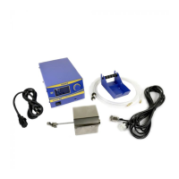
Troubleshooting steps if the unit does not power on.

Tip Not Heating Up

Diagnosing issues when the tip fails to heat, including sensor errors.

Soldering Tip Styles Catalog

Wiring Diagram

Related product manuals