4
15
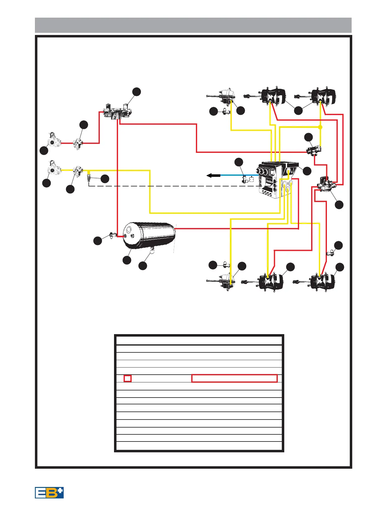
Fig 13
Piping Diagram - Semi , Centre axle Trailers
21
1
11
3
22
4
2
2
2
1
11
11
12
12
11
11
12
11
12
2
2
12
2
21
1
Emergency
Item Description
1 Emergency Coupling
2 Service Coupling
3 Pipe Filter
4 Combined Park and Shunt valve
5 Pressure Switch
6 Air Reservoir
7 Drain valve
8 Test point
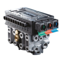
9 EB
+
Assembly
10 Spring Brake Chamber
11 Single Diaphgram Brake Chamber
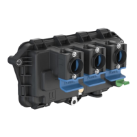
12 Double Check Valve
13 Quick Release Valve
14 Test point simulator
Service
1
3
2
3
8
7
6
8
8
11
10
10
11 10
12
13
4
1
2
3 axle Semi-Trailer - 2 line air brake system - Spring Brake Chambers
Suspension
System
8
2
2S/1M - Side by Side Configuration - Without REV
41
14
9
5
Installation Option Ref Page 22