Do you have a question about the Haldex EB+ Gen 2 and is the answer not in the manual?
Connects the trailer to the towing vehicle for power and data communication.
Detects wheel speed for ABS and other system functions.
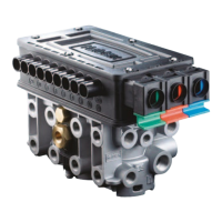
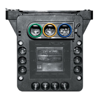
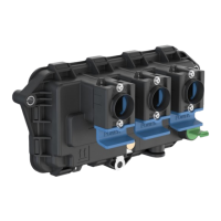
The main control unit housing ECU, EPRVs, and pressure transducers.
Provides basic system information and identification.
Optional unit for displaying system information and diagnostic codes.
Details different configurations for parking brake and emergency functions.
Full EBS function powered via the 7-pin ISO7638 connector.
ABS + ELS function only, without CAN data bus.
Safety backup powering providing ABS function.
Indicates system integrity and faults to the driver.
Identification label for the EB+ Gen 2 system.
Connector for power and CAN data bus connection.
Safety backup power cable connection.
Device for displaying information and diagnostics.
The core assembly including control unit and electro-pneumatic relay valves.
Components for detecting wheel speed and other parameters.
Component that works with the sensor to detect wheel speed.
Automatic reset-to-ride height function.
Lift axle control function.
Monitors brake lining wear.
Trailer roll stability control function.
Describes communication protocols (ISO11898, KWP2000) for diagnostics.
Details information and changes that can be accessed via the Info Centre.
Lists various tests that can be performed for system diagnosis.
Advanced diagnostics and configuration using a PC program.
How the cab warning device indicates system status.
Steps to verify system integrity on power up.
Describes system behavior based on pneumatic brake status during power up.
Initial steps to check system integrity.
Procedure involving applying foot brake and listening to EPRV cycles.
How to read diagnostic codes using the EB+ Info Centre.
Interpreting specific lamp flash sequences for faults.
Trouble codes related to communication loss or ECU timeouts.
Codes for sensor signal or output faults.
Codes indicating intermittent sensor signal issues.
Codes for persistent low sensor output or system faults.
Codes for faults in the brake apply solenoids.
Codes for faults in the EPRV solenoids.
Codes for demand pressure transducer faults.
Codes for delivery pressure transducer faults.
Codes for slow recovery issues on a single wheel.
Codes for reservoir pressure transducer faults.
Codes for suspension pressure transducer faults.
Codes for pressure switch faults.
Codes for CAN bus communication faults.
Codes related to ECU supply voltage.
Codes indicating internal ECU faults or programming issues.
Codes for faults in auxiliary system components.
Codes related to lining wear sensing system.
Codes for lateral accelerometer faults.
Codes for slave valve and modulator faults.
Details functions connected to AUX port 1.
Details functions connected to AUX ports 2 and 3.
Details functions connected to AUX port 4.
Details functions connected to AUX port 5.
Explanation of symbols, wire colours, and important notes.
Illustrates electrical connections between components like sensors, ECU, and ISO connectors.
Defines item numbers, port numbers, and lists pneumatic components.
Diagram showing pneumatic routing for emergency and service functions.
Defines item numbers, port numbers, and lists pneumatic components.
Diagram showing pneumatic routing for this configuration.
Defines item numbers, port numbers, and lists pneumatic components.
Diagram showing pneumatic routing for this configuration.
Defines item numbers, port numbers, and lists pneumatic components.
Diagram showing pneumatic routing for this configuration.
Instructions for checking sensor output and resistance.
Procedure to verify earth continuity.
Checking solenoid resistance for specific functions.
Checks to perform when hubs are removed.
Routine checks for the complete system.
Comprehensive checks for the system and sensors.
Part numbers for various ECU configurations.
Part numbers for ISO7638 connectors and cables.
Part numbers for ISO1185 cable assemblies.
Part numbers for auxiliary cable assemblies.
Part numbers for sensor cable assemblies.
Part number for the EB+ Gen 2 system label.
Part numbers for sensor kits (angled and straight).
Part numbers for the EB+ Info Centre 2 unit.
Part numbers for various cable lengths.
Part numbers for side-of-vehicle installation cables.
Part numbers for diagnostic cable assemblies for side of vehicle.
Part number for ECU position blanking plugs.
Part number for the ISO7638 diagnostic cable.
Part numbers for PC interface, software, and manuals.
Part numbers for cables connecting ECU to interface.
Part numbers for cables from side of vehicle to interface.
Part numbers for lining wear system components.
Part number for external lateral accelerometer.
Part numbers for Info Point cables.
Part numbers for soft docking system kits.
Part number for sensor adjusting tool.
Guidance on using the EB+ Gen 2 for emergency braking and cadence braking warning.
Explanation of how the LWS system indicates brake lining wear.
Description of the trailer roll stability function and its safety role.
How ILAS-E provides traction assist by lifting the front axle.
Explanation of the automatic braking system for bay reversing.
How the Info Point alerts the driver to system faults.
| Brand | Haldex |
|---|---|
| Model | EB+ Gen 2 |
| Category | Diagnostic Equipment |
| Language | English |