Page
EB+ GEN 2 Operator’s guide 2
General Components Guide 3
System Layout 4
Chassis Components 5
System Diagnostics 6
Warning Device, System Check Procedure and
Power-Up Modes 7
Test Procedure 8
Diagnostic Trouble Codes (DTC) 9
ECU Connector Identification 11
Wiring diagram 12
Piping Diagrams 13
Multimeter Reading 17
Recommended Maintenance Schedule 18
Part Reference 19
General Information 21
Your trailer has been fitted with the latest technology Haldex
Electronic Braking System EB
+
Gen 2. This system has been
specifically designed to be effective, reliable and easy to service. The
purpose of this booklet is to describe the components involved and
give you sufficient information to make your use of the system easy.
Concept
EB
+
Gen2 = Antilock Brake System (ABS)
+ Electronic Load Sensing (ELS)
+ CAN (Controller area network ISO11992 data link - computer data
from and to the towing vehicle)
The system reacts to electrical or pneumatic signal from the towing
vehicle. It electronically processes those signals plus signals received
from other sensors on the trailer. In response to those signals the
EB
+
Gen 2 regulates pressure to the brake chambers.
System Description
The position of the various components is shown in Tri-axle layout,
Fig 1. The system is equally compatible with single and tandem axles.
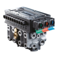
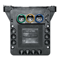
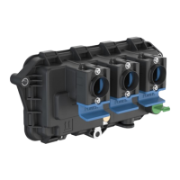
The EB+ Gen 2 system is an integrated construction of an
encapsulated Electronic Control Unit (ECU), Electro pneumatic relay
valves (EPRV’s), over moulded connectors, integrated pressure
transducers and a flash upgradable program memory.
Onset of braking is denoted by presence of a demand on the
ISO11992 data link (CAN) via the ISO7638 connector. Driver demand
pressure is then determined electronically either by the data link or
control line pressure transducer within the EPRV’s assembly.
The demand pressure is then modified using data from the air
suspension (Electronic Load Sensing), and may be further modified
when a wheel speed sensor detects imminent locking of the sensed
wheels (ABS).
The output to the brakes is exercised by the ECU control of the
EPRV’s see Fig 2.
The EB
+
Gen2 ECU also provides up to 5 auxilliary functions such as
automatic reset-to-ride height (COLAS
®
), lift axle control (ILAS
®
-E),
retarder and Stability control.
EB
+
Gen 2 incorporates an odometer facility which measures total
distance of the trailer and its read-out is shown on an optional EB
+
Info Centre unit (Only when powered by the ISO7638 cable).
The EB
+
Info Centre is a side of trailer mounted unit used also for
read-out of diagnostic codes and other information available from the
EB
+
Gen 2 ECU.
The EB
+
Gen 2 also incorporates an enhanced information storage
and retrieval facility.
For the fleet operator, a ‘Fleet Log Reader’ allows the compilation of a
full history of each trailer or long term monitoring.
For the trailer manufacturer, an ‘End-of-line’ Testing (EOLT) to confirm
correct performance of the EB
+
Gen 2 system.
Contents
2