EasyManua.ls Logo

Haldex EB+ Soft Docking - User Manual

Haldex EB+ Soft Docking
72 pages
Print Icon
To Next Page IconTo Next Page
Loading...
Innovative Vehicle Solutions
INSTALLATION GUIDE
Soft Docking
Question and Answer IconNeed help?

Do you have a question about the Haldex EB+ Soft Docking and is the answer not in the manual?

Summary

Notes on Using the Manual

Introduction to EB+ Soft Docking

Chassis Components

Component Layout: 3 Sensors (1 Plane, 1 Offset)

Component Layout: 3 Sensors (1 Plane, 2 Offsets)

Component Layout: 4 Sensors (2 Planes, 2 Offsets)

Component Layout: 4 Sensors (2 Planes, 1 Offset)

Component Layout: 5 Sensors (2 Planes, 2 Offsets)

Component Layout: 5 Sensors (2 Planes, 1 Offset)

Sensor Cables

Sensor Extension Cable

Cable to increase the sensor distance from the ECU. Available lengths: 1.0m, 3.0m, 6.0m.

Sensor Splitter Cable

Y cable to add additional sensors. Dimensions: 0.5m for A, B, and C.

Extension Cable Location

Installation of EB+ Soft Docking ECU

Preparation

Ensure all components are present and outline markers are removed before installation.

Mounting Dimensions

Specifications for the physical dimensions and mounting of the EB+ Soft Docking ECU.

Installation of LED Outline Marker Light

Mounting Dimensions

Specifications for mounting the LED outline marker lights, including screw type and torque.

Installation of Audio Beeper

Mounting Dimensions

Specifications for mounting the audio beeper, including fixing hole and screw type.

Installation of Power Supply Adapter Cable

Connection to Haldex EB+ Gen3 Unit

Details on connecting the auxiliary CAN cable to the EB+ Gen3 unit, including software updates.

Installation into Existing Junction Box

Instructions for inserting the cable into a junction box, connecting wires, and ensuring waterproof installation.

Installation of Ultrasonic Sensor

Minimum Height

Specifies the minimum mounting height for sensors without settings adjustment.

Sensor Offset

Explanation of sensor offset and its use with DIAG+ software for trailer rear gap calculation.

Mounting of Sensor

Mounting Rules

Guidelines for sensor installation: minimum/maximum sensors per channel, balancing channels.

Mounting in Front of Trailer Plate

Details for mounting sensors on the front of the trailer plate, including surface contact.

Mounting Behind Trailer Plate

Details for mounting sensors behind the trailer plate, including surface contact and concentrator use.

Sensor Adjustment

Vertical Mounted Sensor

Sensor Beam Detection Zone

Diagram and dimensions illustrating the sensor's detection area when mounted vertically.

Horizontal Mounted Sensor

Sensor Beam Detection Zone

Diagram and dimensions illustrating the sensor's detection area when mounted horizontally.

Sensor Offset

Installation Error

Configuring EB+ Soft Docking Using DIAG+

Checking EB+ Soft Docking Installation

Removing EB+ Soft Docking from EB+ Gen3

Installing 3-Sensor System Using DIAG+

Installing 3-Sensor System Using DIAG+

Installing 3-Sensor System Using DIAG+

Installing 3-Sensor System Using DIAG+

Installing 3-Sensor System Using DIAG+

Configuring Sensor Channel Offset

Configuring Sensor Channel Offset

Configuring Sensor Channel Offset

Checking for Faulty Installation Using DIAG+

DTC Error Identification

Identifies common DTC errors like incorrect sensor count or EE data mismatch.

Checking for Faulty Installation Using DIAG+

Rectification of Faulty Sensors

Completing EB+ Soft Docking EOLT (3-Sensor System)

Completing EB+ Soft Docking EOLT (3-Sensor System)

Completing EB+ Soft Docking EOLT (3-Sensor System)

Completing EB+ Soft Docking EOLT (3-Sensor System)

Completing EB+ Soft Docking EOLT (3-Sensor System)

Functional Test

Testing Silent Mode

Specific tests for the silent mode functionality of the audio beeper and LED markers.

Operating Instructions

EB+ Soft Docking Indication Modes

Description of different system states and their corresponding audible and visual signals.

Daytime Mode Activation

Night Silent Mode Activation

Conditions of No Detection

Conditions of No Detection

Error Repair

Error Repair; Sensor Diagnosis

Guidance on diagnosing and repairing errors, including sensor issues and warranty implications.

Liability Exclusion

Cable Connections

Excess Cable Management

Painting Recommendations

Masked Areas

Identification of areas to be protected during painting, such as connections, beeper, and sensors.

Part Reference

EB+ Soft Docking ECU

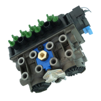
Details of the EB+ Soft Docking ECU, its function, and part number.

LED Outline Marker Lamp (Visual Warning Signals)

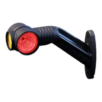
Information on LED outline marker lamps used for visual warning signals, including part numbers.

Outline Marker Lamps and Brake Cables

Sensors and Audio Beeper Cables

Audio Beeper (Audible Warning System)

Ultrasonic Sensor

Sensor Extension Cable

Sensor Splitter Cable

Haldex EB+ Soft Docking Specifications

General IconGeneral
BrandHaldex
ModelEB+ Soft Docking
CategoryAutomobile Accessories
LanguageEnglish

Related product manuals