❑ Installation
18
ESP Primer System Instruction Guide
p/n: 029-0810-01-0
Attach the ground strap from the truck chassis to the priming pump termi-
nal stud to ensure a ground for the motor. See appropriate drawing,
sheet 2.
The ground strap is appropriately sized for a 12 or 24 volt DC, 300 or 150
amp load.
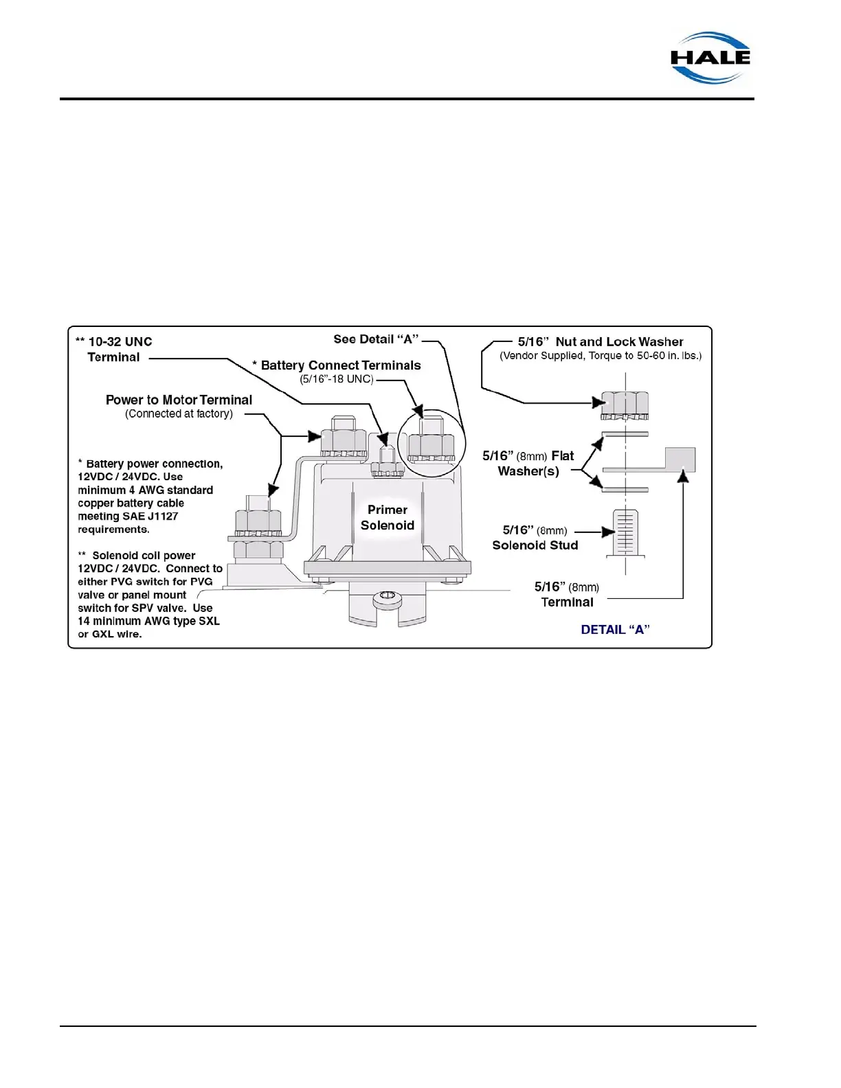
❑ To prevent damage to the solenoid plastic housing, when installing or
removing wire leads, DO NOT apply side loads to the nuts. (See Figure
3-1: “Solenoid Connector Arrangement.”)
Figure 3-1: Solenoid Connector Arrangement
❑ When using a terminal lug on the battery connection with a 5/16” (8 MM.)
diameter hole, the lower washer is not needed.
❑ If the hole is larger than 5/16”, washers are required both above and
below the terminal. Torque to 50 - 60 in. lbs. (6 - 7 N-m) maximum.
DO NOT overtighten to avoid stripping the stud from plastic cap.
❑ The solenoid-to-ground terminal, 10-32 UNC, is factory connected and
torqued to 15 - 20 in. lbs. (1.7 - 2 N-m).
DO NOT overtighten to avoid stripping the stud from plastic cap.
❑ For complete electrical installation instructions, see sheet 2 of drawing
“12 Volt ESP System” on page 54 or see sheet 2 of drawing “24 Volt
ESP System” on page 54.