❑ Maintenance
42
ESP Primer System Instruction Guide
p/n: 029-0810-01-0
22. Secure in place using 7/16”-14 nuts - tighten and torque accordingly nuts.
23. Connect the 3/4” (19 mm) ID vacuum hose from the priming pump to the
hose connection fitting on the Hale SPV assembly.
24. Before placing apparatus into operation, test operation of the Hale SPV.
Conduct vacuum and hydrostatic tests in accordance with department
procedures.
5.3 PVG VALVE REPAIR
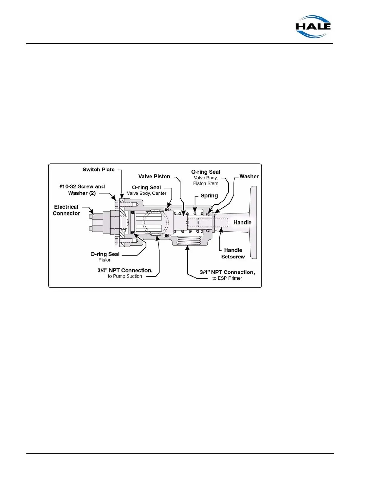
Figure 5-4: Hale PVG Parts Overview
The Hale PVG is designed to provide trouble free service with a minimum of
preventive maintenance. Over time, performance degradation could result from
a worn O-ring seals, causing leaks, a weakened spring, or a failed electrical
switch. (See Figure 5-4: “Hale PVG Parts Overview.”)
A Hale PVG repair kit is available that contains, O-ring seals (3), and the electri-
cal switch. Order Hale repair kit, p/n: 546-1420-00-0. (See Figure 5-5: “PVG
Valve Parts Breakdown.”)
1. Place apparatus out of service in accordance with your departmental
procedures.
2. Make sure the main power supply is deactivated, then disconnect the valve
connection from the main source.