❑ Installation
22
ESP Primer System Instruction Guide
p/n: 029-0810-01-0
❑ Install minimum 14 AWG type SXL or GXL wire (SAE J1128) from one
switch terminal to the priming pump solenoid connection. Secure the
ring terminal to the push button switch using the screws provided.
(See Figure 3-3: “SPV Pushbutton Placard Overview,” on page 21.)
❑ Install minimum 14 AWG type SXL or GXL wire (SAE J1128) from the
other switch terminal to the positive battery power. Secure the ring
terminal to the push button switch using the screws provided with the
switch.
8. Test operation of the Hale SPV and priming pump. Conduct vacuum
and hydrostatic tests in accordance with department procedures,
NFPA1901 or NFPA 1911.
SPV Retrofit Installation, Midship
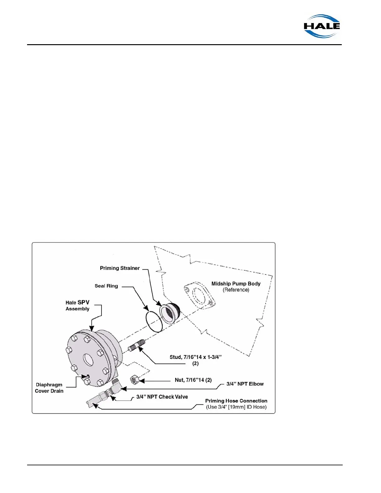
When installing the Hale SPV as a “retrofit” on an existing midship fire pump
use the following procedures. (See Figure 3-4: “Typical SPV / Midship
Pump Installation.”)
Figure 3-4: Typical SPV / Midship Pump Installation
1. Place the apparatus out of service in accordance with departmental
procedures.