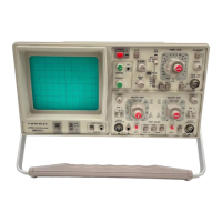
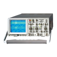
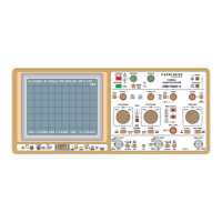
This document serves as a comprehensive manual for the HAMEG HM 203-7 Oscilloscope, a 20 MHz standard oscilloscope designed for reliability, superior performance, and ease of operation. It includes detailed specifications, operating instructions, service information, and circuit diagrams.
Function Description
The HAMEG HM 203-7 is a dual-channel oscilloscope capable of displaying signals up to 20 MHz. It features a built-in component tester, variable holdoff, alternate triggering, and a TV sync separator. The oscilloscope is designed for general service applications, production lines, and technical training facilities due to its multiple display modes, user-friendly front panel, and operational simplicity.
Vertical Deflection:
The instrument offers two vertical channels (Channel I and Channel II) which can be displayed separately, alternately, or chopped. It also supports sum or difference modes (Channel II invertible) and X-Y mode. The frequency range for vertical deflection is DC to 20 MHz (-3dB), with a risetime of approximately 17.5 ns and an overshoot of ≤1%. Deflection coefficients are provided in 10 calibrated steps from 5 mV/div. to 5 V/div. in a 1-2-5 sequence, with an accuracy of ±3% in calibrated position. A variable control allows for adjustment up to 12.5 V/div. Additionally, a Y-magnification x5 (calibrated) function provides a sensitivity of 1 mV/div. ±5% for frequencies up to 3.5 MHz (-3dB). The input impedance is 1 MΩ || 25 pF, with input coupling options of DC, AC, and GD (Ground). The maximum input voltage is 400 V (DC + peak AC). An optional Y-output from Channel I or Channel II is available.
Trigger System:
The trigger system supports automatic triggering from 10 Hz to 40 MHz (≥0.5 div.) and normal triggering with a level control from DC to 40 MHz. Both positive and negative slopes can be selected. An ALT. triggering mode is available with LED indication for trigger action. Trigger sources include Channel I, Channel II, line, and external. Various coupling options are provided: AC (≥10 Hz - 10 MHz), DC (0 - 10 MHz), LF (0 - ≤50 kHz), and HF (≥1.5 kHz - 40 MHz). The external threshold is ≥0.3 V. The oscilloscope also features an active TV-Sync-Separator for line and frame signals.
Horizontal Deflection:
The timebase offers 18 calibrated steps from 0.2 µs/div. to 0.1 s/div. in a 1-2-5 sequence, with an accuracy of ±3% in calibrated position. A variable control allows for adjustment up to 0.25 s/div. With the X-Magnifier x10 function, the timebase can be expanded to approximately 20 ns/div. (±5%). A variable Hold-Off time control is available, adjustable up to approximately 10:1. The X-Amplifier has a bandwidth of DC to 3 MHz (-3dB), with input via Channel II (sensitivity as per Channel II specification). The X-Y phase shift is <3° below 220 kHz. An optional Z input is also available.
Component Tester:
The built-in component tester provides a test voltage of approximately 8.5 Vrms (open circuit) and a test current of approximately 8 mArms (shorted). The test frequency is the line frequency. Connections are made via two 4mm banana jacks, with one test lead grounded (Safety Earth). This feature allows for quick identification of faulty semiconductors and various individual components, both in-circuit and out.
Important Technical Specifications
- Cathode-Ray Tube: D14-364 P43/123 or ER 151-GH/-, rectangular screen with internal graticule, 8x10 cm.
- Acceleration Voltage: 2000 V.
- Trace Rotation: Adjustable on the front panel.
- Calibrator: Square-wave generator ≈ 1 kHz for probe compensation, output 0.2 V and 2 V ±1%.
- Line Voltage: 110, 125, 220, 240 V~ ±10%.
- Line Frequency: 50 Hz to 400 Hz.
- Power Consumption: ≈ 37 W (at 50 Hz).
- Max. Ambient Temperature: +10°C to +40°C.
- Protective System: Safety Class I (IEC 348).
- Weight: Approximately 7.5 kg.
- Colour: Techno-brown.
- Cabinet Dimensions: W 285 mm, H 145 mm, D 380 mm.
- Accessories Supplied: Two 10:1 probes, line cord, and Operators Manual.
Usage Features
- Ease of Operation: The logical arrangement of controls makes the oscilloscope easy to use, even for new users.
- Tilt Handle: A lockable tilt handle allows for multiple viewing angles (0°, 10°, 20° inclination) and horizontal carrying.
- Amplitude Measurements: The applied voltage is determined by multiplying the selected deflection coefficient by the vertical display height in divisions. For exact measurements, the variable control on the attenuator switch must be set to its calibrated detent (CAL). Using a x10 attenuator probe requires multiplying the result by a factor of 10.
- Time Measurements: The duration of a signal period or part of it is determined by multiplying the relevant time (horizontal distance in div.) by the time coefficient set on the TIME/DIV. switch. The variable time control must be in its calibrated position (CAL).
- Risetime Measurement: Risetime is measured between 10% and 90% of the vertical pulse height. For very fast risetimes, the risetimes of the oscilloscope amplifier and probe must be deducted from the measured time value using a specific formula.
- X-Y Operation: Allows for phase difference measurement using Lissajous figures.
- Operating Modes of Vertical Amplifiers: Supports CH.I/II, DUAL, ADD, CHOP., INVERT, and X-Y operation.
- Triggering Modes: Includes Automatic Triggering (AT) for signals >10 Hz to 40 MHz, Normal Triggering (NORM) with LEVEL adjustment, and various coupling options (AC, DC, HF, LF) and sources (CH.I, CH.II, Line, EXT). A TV Sync Separator allows for stable triggering of video signals.
- Holdoff Time: Variable holdoff control helps in obtaining stable displays for complex asynchronous waveforms.
- Probe Compensation: A built-in 1 kHz square wave generator (0.2 Vpp ±1% for x10 probes, 2 Vpp ±1% for x1 probes) is provided for accurate probe compensation.
- Trace Rotation: A potentiometer accessible on the front panel allows for correcting minor misalignments of the trace with the horizontal center line of the graticule, which can occur due to the Earth's magnetic field.
Maintenance Features
- General Maintenance: Regular checks of the oscilloscope are recommended. The instrument case should be cleaned with a soft cloth, and the screen with a mild cleaning solution.
- Mains/Line Voltage Switching: Instructions are provided for switching the instrument to different mains/line voltages (110, 125, 220, 240 V~) by changing the fuse and adjusting the voltage selector.
- Instrument Case Removal: Detailed instructions for safely removing the rear cover and chassis for maintenance or repair. Emphasizes disconnecting power and discharging capacitors.
- Safety Precautions: Strict adherence to IEC Publication 348 safety requirements is mandatory. Warnings are provided regarding interruption of the protective conductor, high voltages, X-ray emissions from the CRT, and handling of the CRT.
- Operating Voltages Check: Instructions for checking the DC operating voltages, including the +12V adjustable voltage and other fixed voltages.
- Brightness and Focus Adjustment: Procedures for adjusting maximum and minimum brightness and astigmatism control.
- Trigger Threshold Adjustment: Steps for checking and adjusting the trigger threshold.
- Troubleshooting: General guidance for troubleshooting the instrument.
- Component Replacement: Advice on using original or equivalent parts, especially for selected semiconductors. Information required for ordering replacement parts is specified.
- Power Transformer Replacement: Detailed instructions for replacing the mains/line transformer, including terminal sequence, safety regulations, and post-replacement checks.
- Adjustments: General advice on performing small corrections and adjustments using circuit diagrams and the adjusting plan. A complete recalibration should only be attempted by experienced operators with appropriate measuring instruments.
- Test Instructions: Comprehensive test procedures for various components and functions, including the Cathode-Ray Tube, vertical amplifier, transmission performance, operating modes, triggering, timebase, holdoff time, component tester, and mains/line voltage checks.
- In-Circuit Tests: Guidelines for performing in-circuit tests with the component tester, emphasizing safety precautions such as disconnecting power and signals.