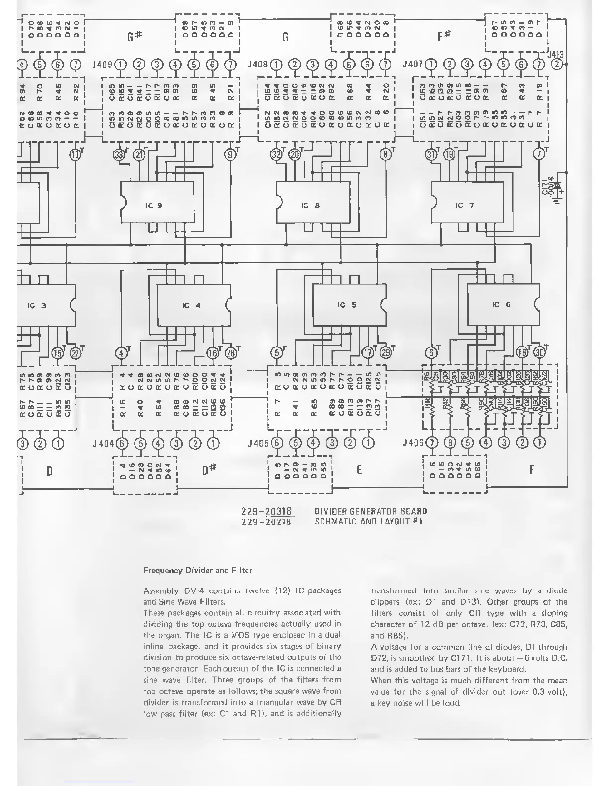
229-20318 DIVIDER GENERATOR
BOARD
229
-20218
SCHMATIC
AND LAYOUT*!
Frequency
Divider and Filter
Assembly
DV-4
contains twelve (12) IC
packages
and Sine Wave Filters.
These packages contain all circuitry associated
with
dividing the top octave frequencies
actually used in
the organ. The IC is a MOS
type enclosed in a dual
inline package,
and it provides six stages of binary
division to
produce six octave-related outputs of the
tone generator.
Each
output
of the IC is connected a
sine wave
filter. Three groups of the filters from
top
octave operate
as
follows; the square wave
from
divider is transformed into a triangular
wave
by
CR
low pass
filter (ex:
C1
and R1), and
is additionally
transformed
into similar sine waves by a diode
clippers (ex: Dl and D13). Other groups Of the
filters consist of only CR type with a sloping
character of 12 dB per octave,
(ex:
C73, R73, C85,
and R85).
A voltage for a common line of diodes, Dl through
D72, is smoothed by
C171.
It is about
-6
volts D.C.
and is added to bus bars of the keyboard.
When this voltage is much different from the mean
value
for
the
signal of divider
out (over 0.3 volt),
a key noise will
be loud.