L E D.
P.L.+(7>
|
CURRENT
OUT,
>
1
15MA
-®—
-S>
AC
27V
COM
NOTES
1 Dl 3DG-O1023
182C1
02 306-01024
1B2Z1
D3 337-02DQ1 02Z-6.2A
ffi
305-03027
2SC1226A
02 3D5 -0304D
2SC9450
03.4
305-01008
2SA733Q
05.6
305 01 01 3 2SA49DV
2
UNLESS
OTHERWISE SPECIFIED
AIL RESISTORS ARE IN
0HMS.±5!i.1/4WATT
ALL CAPACITORS ARE IN
MICROFARADS
3
ft) SYMBOL
DENOTES NUMBERS IN
TERMINALS.
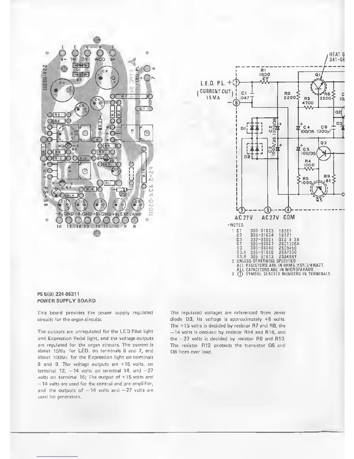
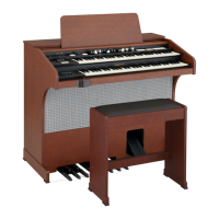
PS-5(B) 224-05311
POWER
SUPPLY
BOARD
This board
provides the power supply
regulated
circuits for the organ circuits.
The tutputs are
unregulated for the I.ED
Pilot light
ann Expression
Pedal light, and the voltage
outputs
are regJated tor tne nrt|a!i circuits. I he current is
about 1bWa
for
LED. on terminal* 6 and 7, am)
about
lOOWa
for the Expression litfht on terminals
8
and 9. The voltage outputs are
'15 volts, on
terminal 12.
14 volts
on
terminal
14,
and 27
volts on
terminal
16;
The
output
of
-15
volts
and
14
volts a'e used
for the control and pro-amplilwr,
and the outputs
of
—14
volts and
—27
volts
are
used
for generators.
The regulated voltages are referenced
from
zener
diode D3, its voltage is approximately
+6
volts.
The
+15
volts is decided by resistor R7 and R8, the
-14
volts is decided by
resistor
R14
and
R16,
and
the
-27
volts is decided by resistor
R9
and R10.
The
resistor R12
protects the transistor
0.5
and
Q6 from over load.