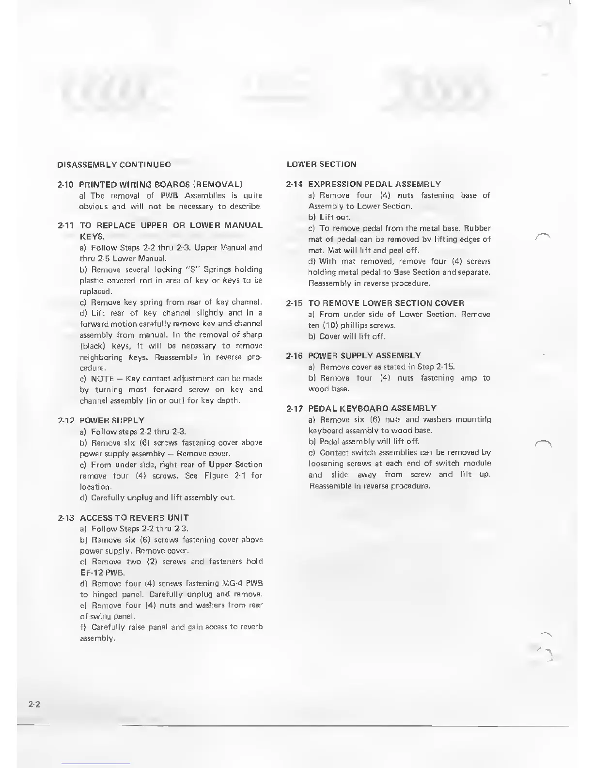
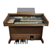
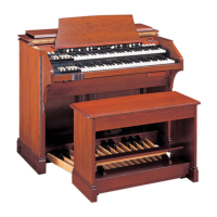
DISASSEMBLY CONTINUED
LOWER SECTION
2-10 PRINTED WIRING BOARDS (REMOVAL)
a)
The removal of PWB Assemblies is quite
obvious and will not be necessary to
describe.
2-11
TO
REPLACE UPPER OR LOWER MANUAL
KEYS.
a) Follow Steps
2-2
thru
2-3.
Upper Manual and
thru
2-5
Lower Manual.
b)
Remove several locking
"S"
Springs holding
plastic
covered rod in area of key or keys to be
replaced.
c)
Remove key spring
from rear of key channel.
d) Lift rear of key
channel slightly and in a
forward
motion carefully
remove key and channel
assembly from manual. In the
removal of sharp
(black) keys,
it will be necessary to remove
neighboring keys. Reassemble in
reverse pro-
cedure.
c)
NOTE
-
Key contact
adjustment can be made
by
turning most forward
screw on key and
channel assembly (in or out)
for key depth.
2-12
POWER
SUPPLY
a) Follow steps
2-2
thru
2-3.
b) Remove six
(6)
screws
fastening cover above
power supply assembly
-
Remove
cover.
c)
From under side, right rear
of Upper Section
remove four
(4)
screws. See
Figure
2-1
for
location.
d) Carefully unplug and lift
assembly out.
2-14 EXPRESSION PEDAL ASSEMBLY
a)
Remove four
I
Assembly
to
Lower
b)
Lift
out.
c) To
remove
pedal
mat of ped: be r
fastening
base of
the
metal base. Rubber
>ved by lifting edges of
.. M:li
lift a
d) With mat removed, remove four
(4)
screws
holding
metal pedal to Base Section and separate.
Reassembly in reverse procedure.
2-15
TO
REMOVE LOWER SECTION COVER
a)
From under side of Lower Section. Remove
ten
(10)
phillips screws.
b) Cover will lift
off.
2-16 POWER SUPPLY ASSEMBLY
a)
Remove cover as stated in Step
2-1
5.
b)
Remove four
(4)
nuts fastening amp to
wood base.
2-17
PEDAL
KEYBOARD ASSEMBLY
a)
Remove six
(6)
nuts and
washers mountirlg
keyboard assembly to wood base,
bi
Pedal assembly will lift off.
c)
Contact switch assemblies can
be removed by
loosening screws at
each end of switch module
and
slide
away
from screw and lift up.
Reassemble in reverse procedure.
2-13
ACCESS TO REVERB UNIT
a)
Follow Steps
2-2
thru
2-3.
b) Remove six
(6)
screws
fastening cover above
power
supply. Remove cover.
c)
Remove
two
(2)
screws and fasteners
hold
EF-12 PWB.
d)
Remove four
(4)
screws fastening MG-4
PWB
to
hinged panel. Carefully unplug
and remove.
e) Remove four
(4)
nuts and
washers from rear
of swing panel.
f)
Carefully
raise
panel and gain access to
reverb
assembly.