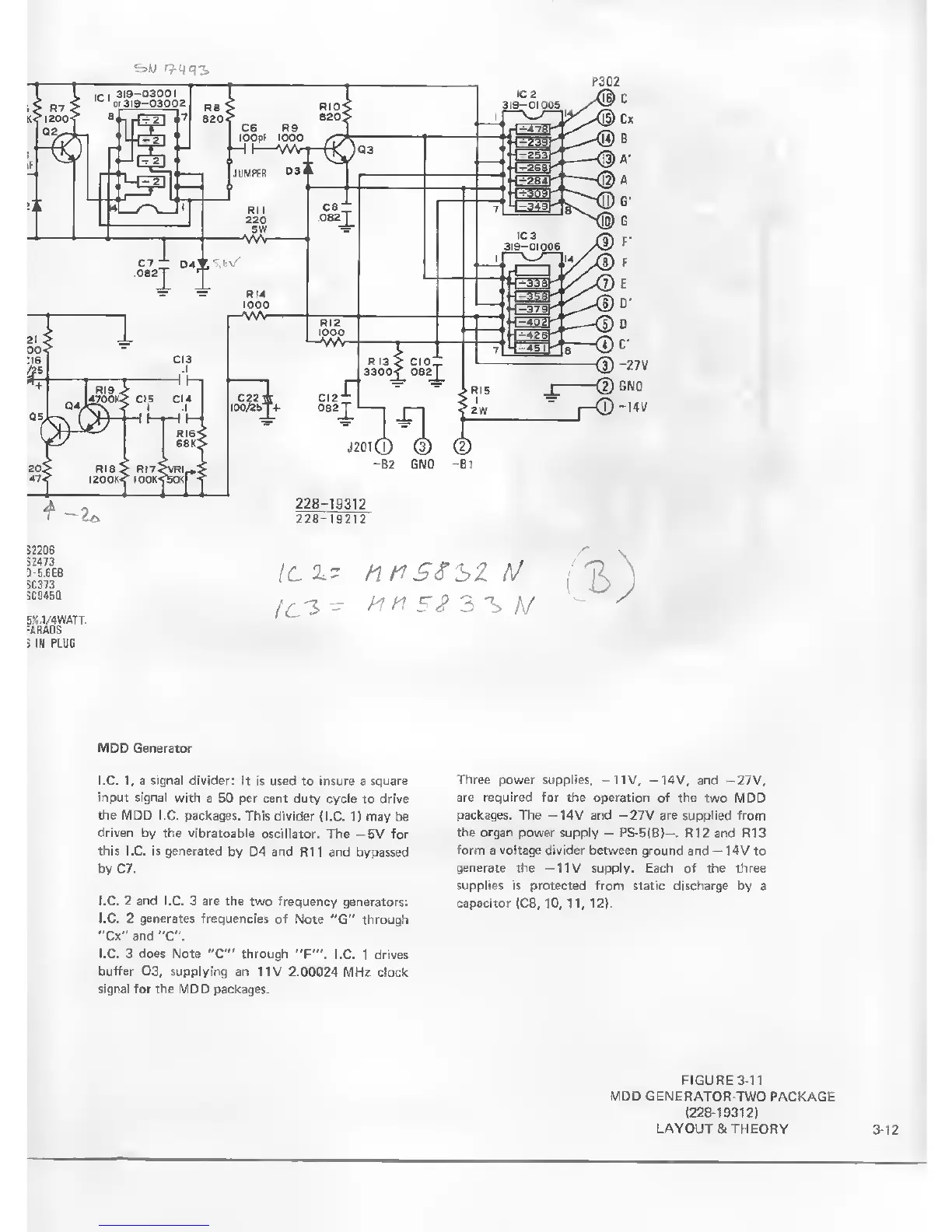
MDD
Generator
I.C. 1, a signal divider: It is used
to
insure
a
square
input
signal with a
50 per cent duty cyeie
to drive
the MOD I.e. packages.
This divider
{I.C.
1
)
may be
driven by the vibratoable
oscillator.
The
—
5V for
this I.C. is generated by
D4
and
R 1 1 and bypassed
by C7.
I.C. 2
and
I.C. 3 are the two frequency
generators:
I.C.
2
generates frequencies
of
Note "G" through
"Cx"and
"C".
I.C. 3 does Note
"C"
through
"F"\ I.C. 1 drives
buffer
03,
supplying an
11V 2.00024
MHz clock
signal for the
MDD packages.
Three power
supplies, -11V,
-14V,
and
-27V,
are required
for the operation of the
two MDD
packages. The —14V and —27V are supplied from
the organ power
supply
-
PS-5IB}-.
R12
and
R13
form
a
vottage
divider between ground and
-14V to
generate
the -11V supply. Each of the three
supplies is protected from static discharge by a
capacitor (C8,
10, 11,
12].
FIGURE
3-1
1
MDD GENERATOR-TWO
PACKAGE
(228-19312)
LAYOUT & THEORY 3-12