J802
J
803 J805
EXPRESSION
EXT. IN MASTOR VOLUME
D1
THROUGH
03
306-0101
7 1S2473
01.07508
305-
01 006 2SA493GR
02 THROUGH D6 305-03023
2SC1
DOOGR
09 30B-D3041 2SC509Y
QIO
305-010H
2SA509Y
IC1
319-23D01
pPCI
51A
UNLESS OTHERWISE SPECIFIED-
ALL RESISTORS ARE IN
OHMS.+
5%.1/4WATT.
ALL
CAPACITORS
ARE
IN MICROFARADS,
AND
luF THROUGH
4
7(jF ARE
USED TANTALUM.
Q
SYMBOL DENOTES NUMBERS IN PLUG.
tions:
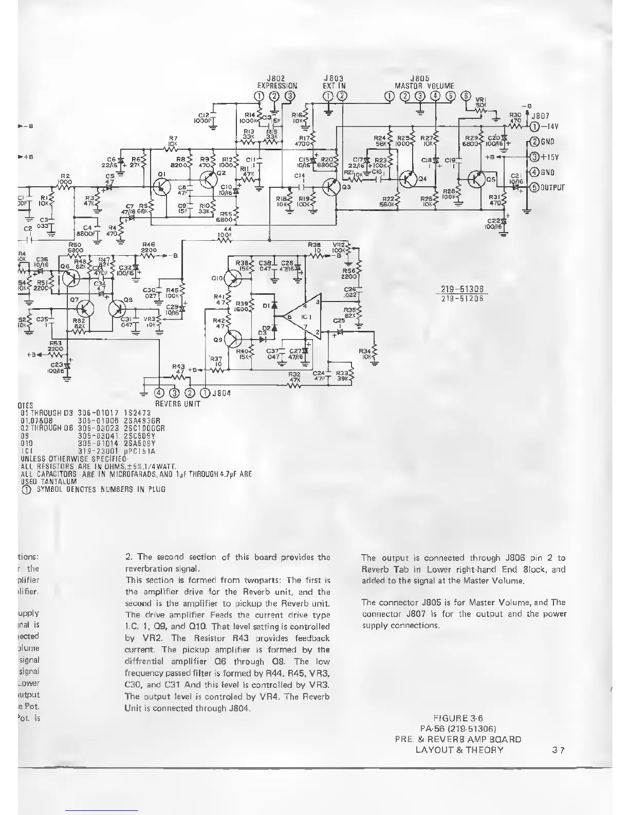
2. The second section of this
board
provides
the
The output is connected through J806 pin 2 to
the reverbration
signal.
Reverb
Tab in Lower
right-hand End Block, and
'
This section is
formed
from twoparts: The first is
added to the signal at
the
Master Volume.
the amplifier drive for the Reverb
unit, and the
second is the amplifier
to pickup
the Reverb
unit.
The connector
J805 is
for Master Volume, and The
upply
The drive amplifier Feeds the current drive
type
connector J807 is for the output and
the power
(OX
is
I.C.
1,
Q9, and QIO. That level setting is controlled
supply connections.
ected
by VR2. The Resistor R43 provides feedback
plume
current. The pickup amplifier is formed
by
the
signal
diffrential amplifier Q6 through CIS.
The
low
frequency
passed filter is formed
by R44, R45, VR3,
C30, and C31 And this level is controlled
by VR3.
utput
The output level is controled
by VR4.
The Reverb
ePot.
Unit is connected through
J804.
>ot- is FIGURE
3-6
PA-56
(219-51306)
PRE.
&
REVERB
AMP BOARD
LAYOUT St THEORY
3-7