H27-10
919-518a 10.01.15
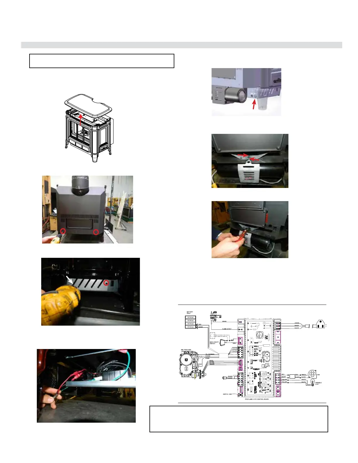
OPTIONAL FAN INSTALLATION
1. Turn o the stove and allow it to return to room temperature.
2. Lift o the cast top and place it on a soft surface.
3. Take o the back access panel by removing 2 screws as
shown in the picture below.
4. Remove left side access panel (when facing the unit) by
removing 2 screws.
5. Bring the fan assembly near to the unit.Connect the black
and red wires from the fan to the IFC’s black and red wire
through connectors.
6. Secure the fan assembly wire with a strain relief on the back
of the left side access panel.
7. Loosen the 2 bolts on fan assembly and slide the fan into the
slots provided on the unit.
8. Once the fan assembly is tted into the assigned slots, tighten
the bolts with a wrench.
9. Reinstall the left side access panel, back access panel and
the cast top.
10. Reconnect gas and power supply.
11. To remove fan - reverse steps.
NOTE: It is recommended to connect wires rst – then install the
fan assembly to allow for more room when installing onto the unit.
WARNING: Electrical Grounding Instructions
This appliance is equipped with a three pronged (grounding) plug for your protection
against shock hazard and should be plugged directly into a properly grounded three-
prong receptacle. Do not cut or remove the grounding prong from this plug.
Strain Relief
RESET
SWITCH
Thermostat( Optional)
(Millivolt)