48 | Hampton
®
H27E-11 Direct Vent Freestanding Gas Stove
maintenance
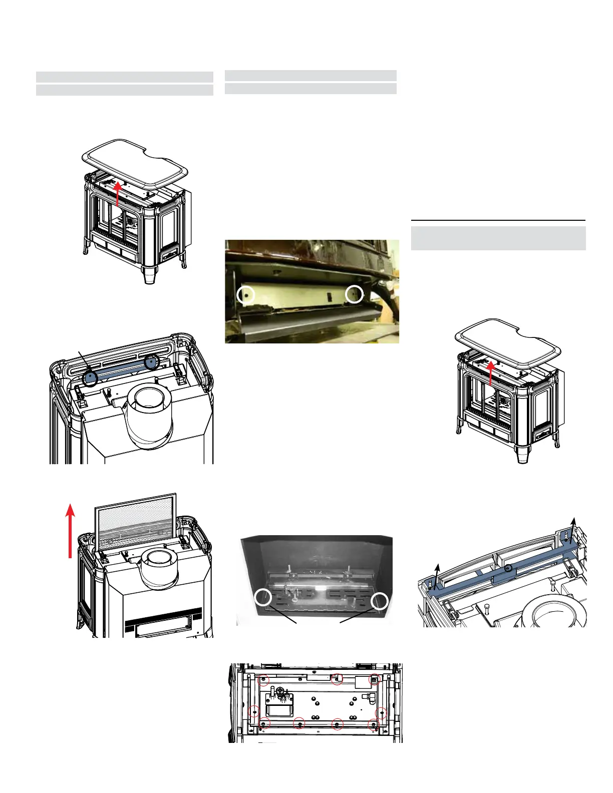
Safety Screen
Removal / Installation
1. Turn off stove and allow ot return to room tem-
perature.
2. Lift off cast top and place on a soft surface.
3. Remove 2 bolts to remove safety screen retaining
bracket (secured to the back of the cast front).
4. Slide safety screen up to remove.
5. To install, reverse steps.
Retaining bracket
12. Carefully lift the valve tray assembly up and out
of the unit to remove.
13. Replace with new valve assembly and reverse
steps to reinstall.
Valve Assembly
Replacement
If your valve requires maintenance or replacement,
use the following instructions:
Note: Always close off the gas and elec-
trical supply before removing the
valve.
1. If optional fan is installed, disconnect power
source to stove.
2. Open the front panel and remove the cover
plate by removing two screws.
3. Disconnect gas line to stove.
3. Disconnect gas line to stove.
4. Disconnect 3/8" NPT pipe from 90
o
elbow on
valve or flex connector.
5. Disconnect 3 wires from spark igniter assembly.
6. Lift off the Cast Top and remove the Cast Front
and glass door (see detailed instruction in this
manual).
7. Carefully move the light bracket out of the way.
8. Carefully remove the logs and embers.
9. Remove burner by removing the 2 screws on
each side and then lifting the burner tray out.
Note: Use a magnetic type screwdriver if pos-
sible.
Screws
10. Remove 10 screws to remove valve tray.
Accent Light Bulb
Replacement
1. Turn off stove and allow to return to room tem
perature.
2. Shut off electrical supply
3. Lift off cast top and place on a soft surface.
4. Loosen bolts securing cast front–slide light as-
sembly bracket upward to release.
5. Remove one (1) screw to remove bulb housing.
Lift light assy bracket off bolts to replace bulb
Remove one screw in location shown
6. Replace bulb.
Note: Oils from hands will shorten the life of the
bulbs, do not handle bulbs with bare hands.
7. Reverse steps to reinstall.
11. Disconnect the following wires prior to removing
valve assembly:
a) Spark wire from IFC board (X2)
b) Flame detect wire from IFC board (X3)
c) Stepper motor wire harness from IFC board (X6)
d) Orange wire from gas valve (EV1)
e) Green wire from gas valve (EV2)
f) Yellow ground wire located under where orange
wire was disconnected on gas valve.