34 | Hampton
®
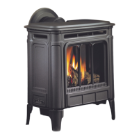
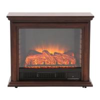
H27E-11 Direct Vent Freestanding Gas Stove
installation
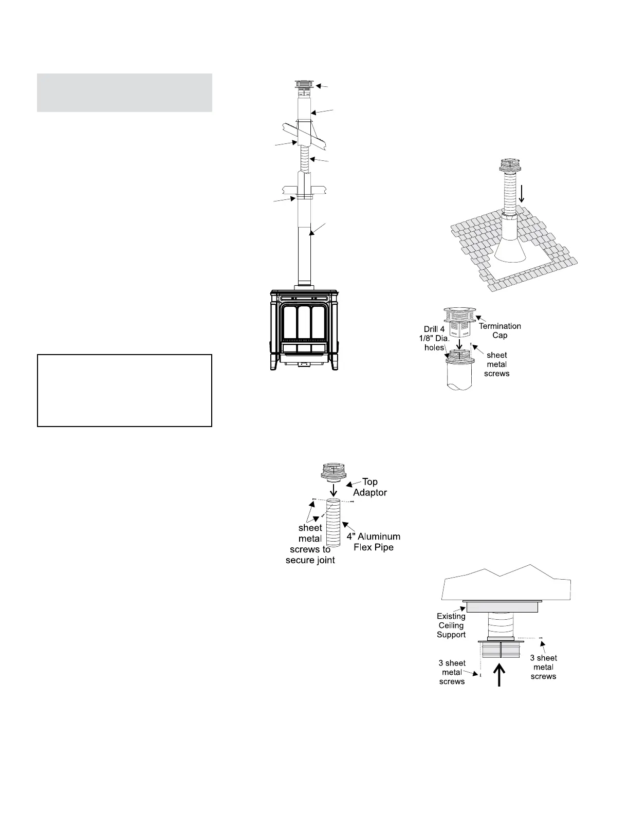
Termination
Cap
Top Adaptor
Existing
Metal
System
Aluminum
Flex Pipe
Retro
Connector
Any Simpson
Dura-Vent
black direct vent
pipe plus an
adjustable length
to make a
proper connection.
Converting Class-A
Metal Chimney to
Direct Vent System
Prior to installation and connection of the vent
system to a factory-built chimney, the chimney
must be inspected and thoroughly cleaned by
a qualified service person, such as a certified
chimney sweep or home inspection service.
The direct vent system must not be connected
to a damaged factory-built chimney.
For factory built, zero clearance chimneys
cleanout doors and caps or plugs for cleanout
tee fittings and ash dumps shall be secured
in place and sealed before installing a Direct
Vent system within the chimney.
If the appliance shuts off during operation,
contact a qualified service person to determine
if a negative pressure and/or leaky chimney
condition exists. Do not operate the appliance
until the problem is corrected.
Approved for US Installations Only
The use of an existing chimney as an air intake
is not covered under the ANSI Z21.88-2014, CSA
2.33-2014 test methods and the resulting ITS/
WHI product certification. The code Authority
Having Jurisdiction must be consulted prior to
proceeding with this installation method.
Converting a Factory Built Metal
Chimney
Important: If converting this appliance to a
Factory Built Metal Chimney, the IPI/CPI
switch on the handheld remote control/
transmitter must be turned to CPI (Continu-
ous Pilot Ignition) at all times. This will avoid
nuisance pilot outages during operation
of this appliance. See Remote manual for
setup of this IPI/CPI switch.
1) Remove the existing chimney cap.
2) Measure the distance from the top end of the
chimney to the bottom of the ceiling support
box, add 3" (76mm) to this measurement, and
cut a section of the 4" flex pipe to that length
(the flex should already be extended to its
nominal length).
4) Pass the flex pipe down through the center of
the chimney system, and center the adaptor
on the top of the chimney pipe. Drill four 1/8"
diameter holes through the adaptor and into the
chimney top. Insure that you are in fact, drilling
into the metal on the chimney. Twist-lock the
Termination Cap onto the Adaptor. (Diagram 3
and 4).
Diagram 1
Diagram 2
Diagram 3
5) Pull the flex pipe down through the ceiling
support box, until it protrudes approximately
3" (76mm). Connect the flex pipe to the Retro
Connector by slipping it into the
4-3/4" diameter sleeve on the top side of
the Connector. Use 3 sheet metal screws
to assemble these two parts.
6) Push the flex pipe back up into the ceiling
support box, center the Retro Connector, and
attach it to the support box, or decorative
sleeve for double wall solid packed pipe, with
the sheet metal screws (supplied). The holes
in the Retro Connector are pre-punched.
Diagram 5.
Diagram 4
Diagram 5
3) Connect the end of the flex pipe section to the
underside of the Top Adaptor using 3 sheet
metal screws. Diagram 2.
7) The connection between the appliance and
the Retro Connector may be completed with
sections of black direct vent pipe, together
with an adjustable length.