HAMWORTHY HEATING LTD
20
FLEET V series
500001217/D
8 CONTROLS OPERATION
visible on the display via the LMU programme. This MUST
be carried out with the boiler running at maximum firing rate.
The 20°C ΔT condition across the boiler must be set as follows;
1 Run boiler at maximum rate.
2 Monitor flow temperature (displayed on main screen of HMI).
3 As boiler flow temperature rises, between 60°C & 80°C , press info button (to enter information mode) then
hold down up/down arrows for 3 seconds (to enter extended information mode) use + button to scroll to b1
which displays boiler return temperature.
4 Within the case, locate the ball valve on the return pipe of the boiler, and then adjust to give 20°C
differential between flow and return temperature. Opening the valve will decrease the differential/closing the
valve will increase the differential.
Press mode button to exit back to main screen and check flow temperature. It may be necessary to repeat the
sequence several times to ensure an accurate 20°C delta T is set.
Note.
E164 error code = flow switch interrupt (too little/no flow through boiler).
E154 error code = Delta T supervision active (too little flow through boiler).
7.8 User Instructions.
When the boiler is fully commissioned, the owner or their representative should be made aware of the lighting-up
and operating instructions. A practical demonstration should be given describing each functional step. This
Installation and Commissioning guide, the servicing instructions manual and the user’s instructions should then be
handed over and be kept in a safe place for future reference.
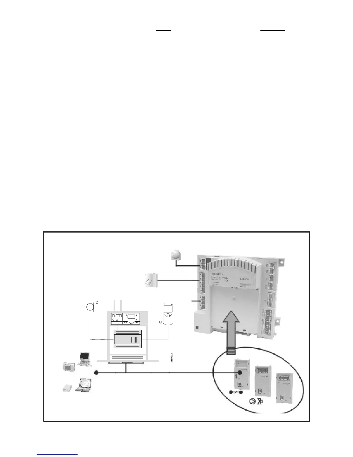
Figure 8.2 - System configuration of boiler control (LMU) & system peripherals