6
E
N
G
L
I
S
H
OUTLET DEWPOINT
DEW POINT
TEMPERATURE MULTIPLIER
°F °C
38 3 1.0
40 4 1.1
45 7 1.2
50 10 1.3
COOLING MEDIUM*
AMBIENT
TEMPERATURE MULTIPLIER
°F °C
80 27 1.12
90 32 1.06
100 38 1.00
110 43 0.94
INLET COMPRESSED AIR CONDITIONS
INLET INLET TEMPERATURES
PRESSURES 80
°F90°F 100°F 110°F 120°F
psig kgf/cm
2
27°C32°C38°C 43°C49°C
50 3.5 1.35 1.05 0.84 0.69 0.56
80 5.6 1.50 1.17 0.95 0.79 0.66
100 7.0 1.55 1.23 1.00 0.82 0.70
125 8.8 1.63 1.31 1.07 0.91 0.74
150 10.5 1.70 1.37 1.13 0.95 0.80
175 12.3 1.75 1.42 1.18 0.99 0.84
200 14.0 1.80 1.47 1.22 1.03 0.89
3.1 Condenser coil—
Clean off accumulated dust and dirt monthly.
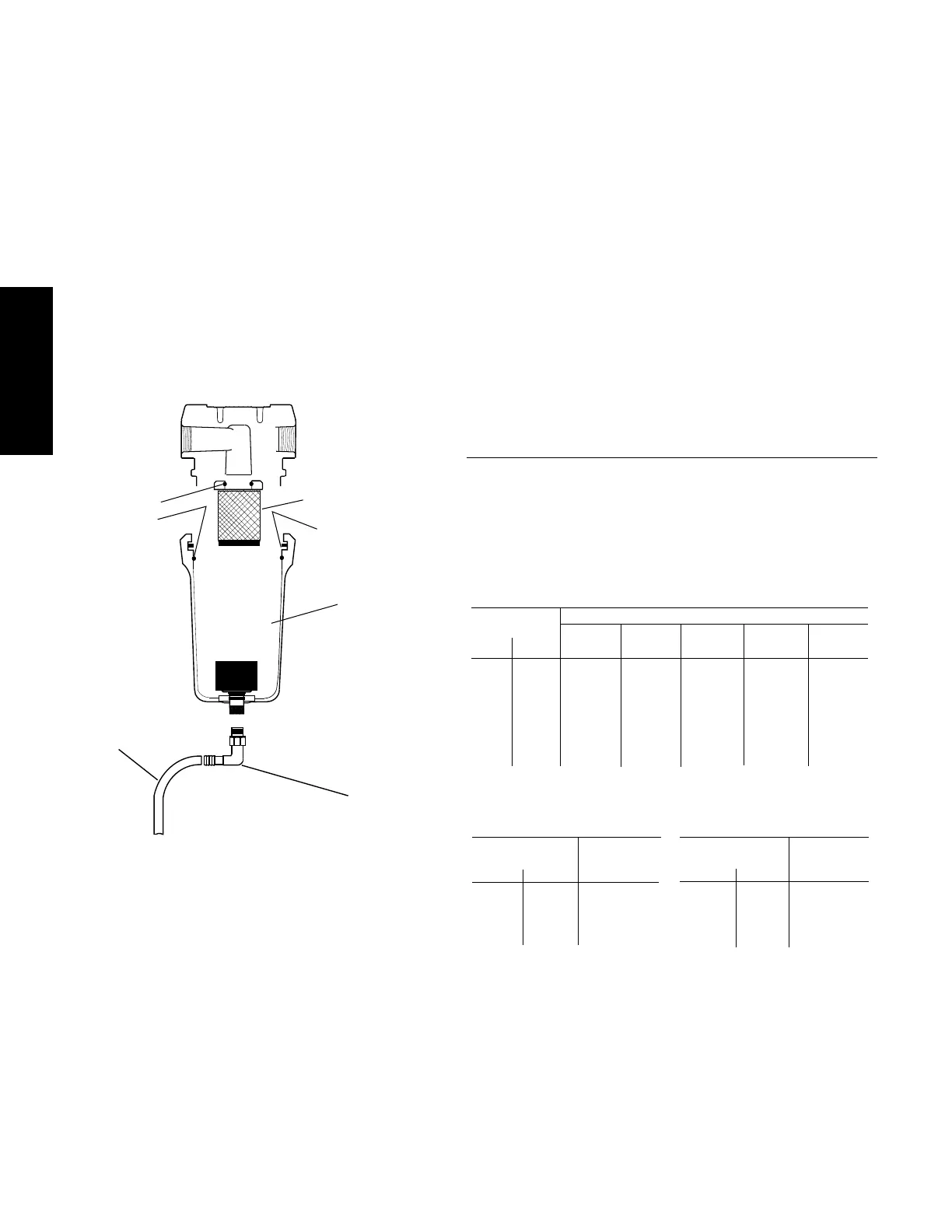
3.2 Moisture separator—
Replace filter element when pressure drop across
dryer is excessive or annually.
3.3 Check separator daily to be sure automatic drain is
discharging.
3.4 Replace drain mechanism annually.
To facilitate service, maintenance kits are available.
3.0 Maintenance Sizing
Determining dryer capacity at actual operating
conditions
To determine the maximum inlet flow capacity of a dryer
at various operating conditions, multiply the rated
capacity from Table 1 by the multipliers shown in Table 2.
Example: How many scfm can an air-cooled model 125
handle when compressed air to be dried is at 80 psig and
90°F; ambient air temperature is 80°F; and a 35°F dew
point temperature is desired?
Answer: 125 x 1.17 x 1.12 x 1.0 = 163.8 scfm.
TABLE 2
Air capacity correction factors (Multipliers)
25 35 50 75 100 125 150
MODEL
Rated capacity of 60 Hz 25 35 50 75 100 125 150
air-cooled models (scfm) 50 Hz 21 29 42 63 84 105 125
TABLE 1
Rated capacity (scfm) and pressure drop @ 100 psig inlet
pressure, 100°F inlet temperature, and 100°F ambient
temperature
*Air-cooled models; water-cooled models use 1.15 multiplier if cooling water is
below 35°C, 95°F.
Element o-ring
Separator Element
Bowl o-ring
Drain Mechanis
Wave Spring
Tube
Hose
Barb
 Loading...