17
INSTALLATION
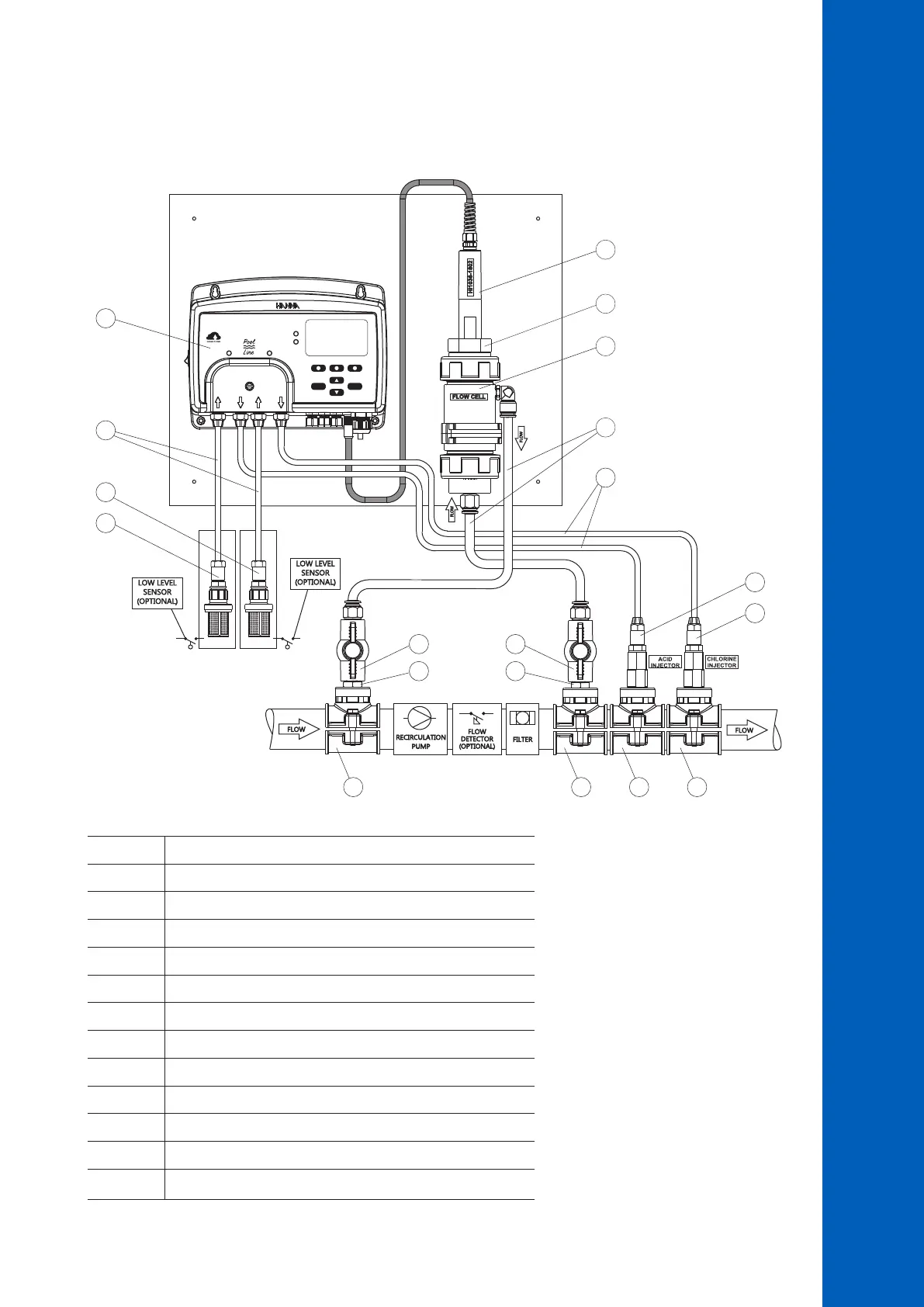
Flow Cell Installation Overview & Components Table
Below is an illustrated reference of a generic, flow cell installation scheme with the relevant components.
The maximum pressure of the flow cell system is 3 atm (44 psi).
HELP
MENU
ChlorinepH
SWIMMING POOL CONTROLLER
SERVICE
STATUS
BL123
ACID TANK CHLORINE TANK
1
2
3
4
5
6
8
7
9 9
10
10
8
12 12 12 12
11 11
Position Component description
1 Pool controller
2 pH/ORP/temperature electrode
3 Flow cell
4 Flow cell adapter
5 Flow cell tubing
6 Flexible tubing for pump input
7 Rigid tubing for pump output
8 Aspiration filter
9 Flow cell valve
10 Injector, 1/2” thread
11 Plastic nipple, 1/2”
12 Injector saddle for pipe, using 1/2” thread

 Loading...


