13
DESCRIPTION
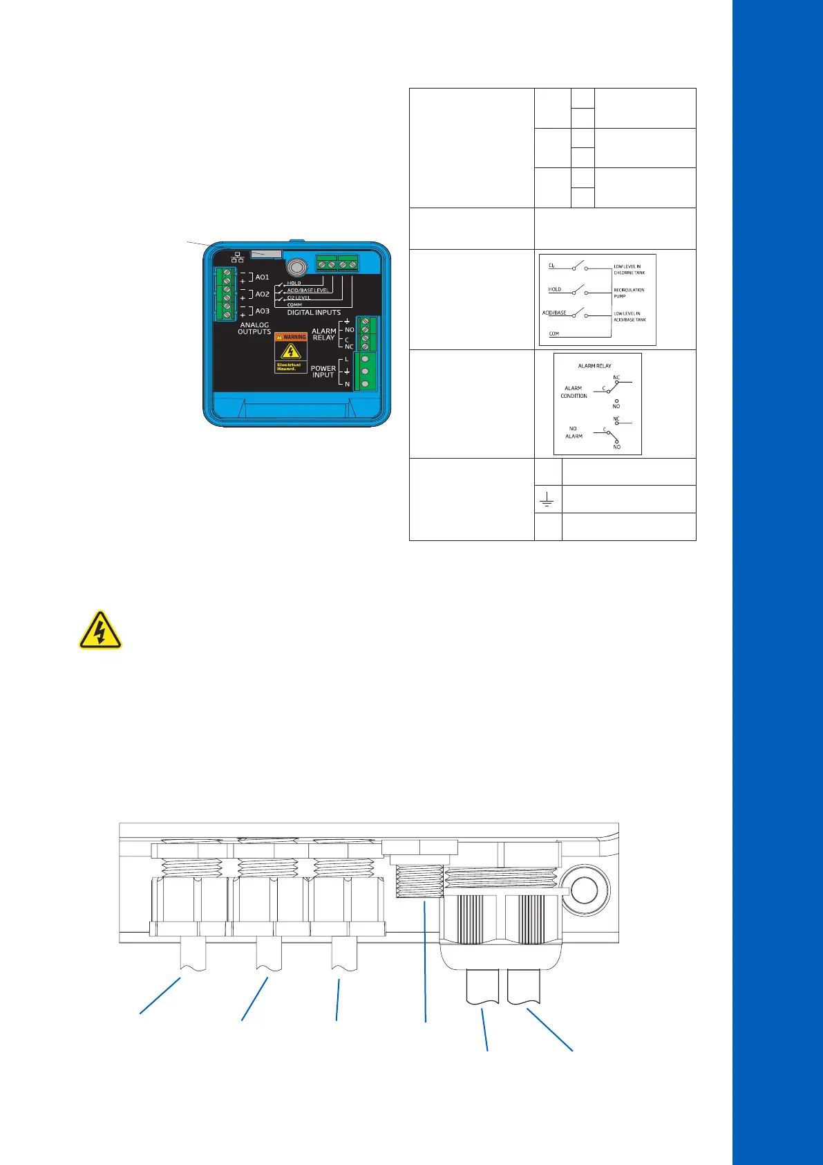
5.3. WIRING
ANALOG OUTPUTS
(BL121 & BL123)
A01
+
4 - 20 mA OUT
–
A02
+
4 - 20 mA OUT
–
A03
+
4 - 20 mA OUT
–
ETHERNET
(BL122 & BL123)
RJ-45 connector
DIGITAL INPUTS
ALARM RELAY
POWER INPUT
L Line
Protective Earth
N Neutral
Note: The analog outputs – AO1, AO2, AO3 – are available only for BL121 & BL123.
The Ethernet connector is available only for BL122 & BL123.
Warning! Always disconnect the Pool Controller from power when making electrical connections. Do not access
the larger rear panel. User-serviceable terminals are found in the small sub panel only.
There are four openings for wiring:
• The left rear openings, for power and digital input wiring
• The left front opening, for alarm relay wiring
• The larger right opening, for analog output wiring (BL121& BL123) and the ethernet cable (BL122 & BL123)
• Sensor wiring is made using the connector with threaded seal
Note: Do not run power cabling through the same opening as other cables.
All unused openings must be sealed with conduit plugs.
Gland seals for
inputs cable
Alarm relay cable Sensor input
Analog outputs cable
(BL121 & BL123)
Ethernet cable
(BL122 & BL123)
Power cable

 Loading...


