21
INSTALLATION
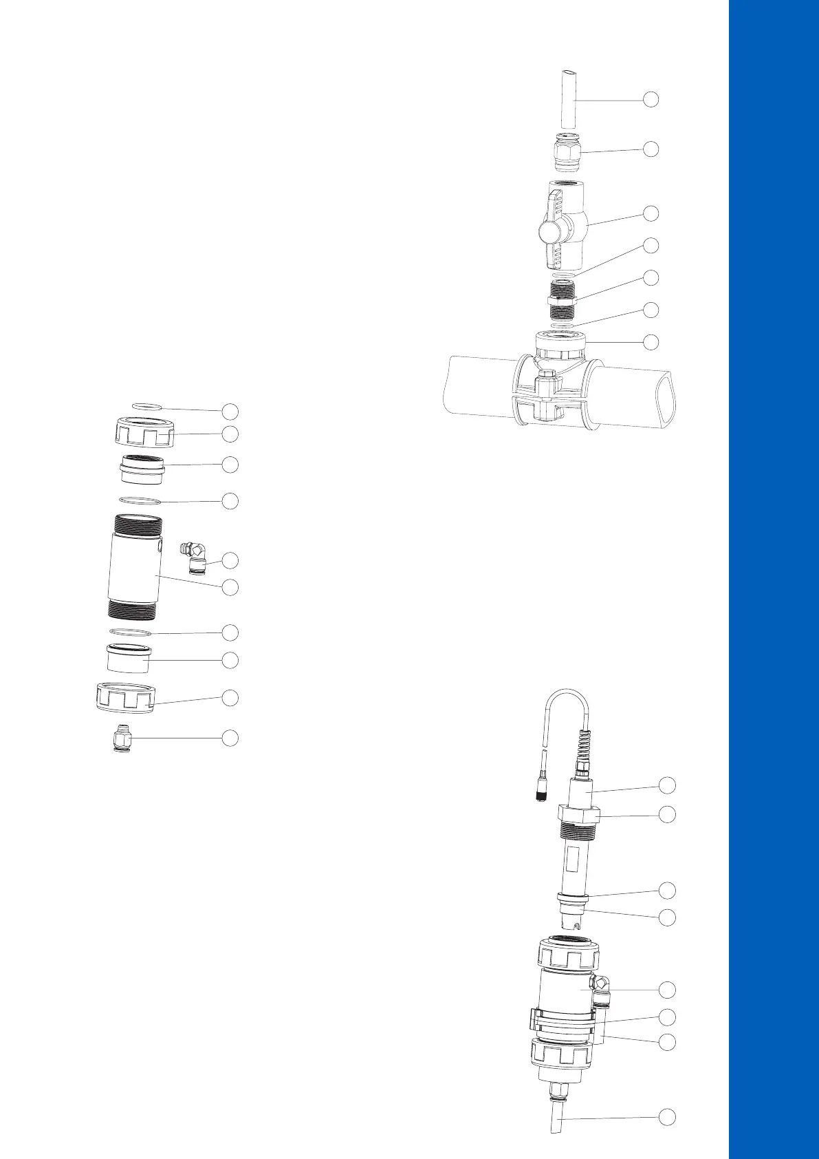
6.7. FLOW CELL INSTALLATION
In a flow cell configuration the water flows from the inlet valve to the flow cell
and returns in the line via the outlet valve.
PART A Preparing the inlet and outlet valve assemblies
• Mount the saddle for flow cell inlet and outlet valve (follow mounting
recommendations for saddle).
• Sparingly lubricate two O-rings (2) with a thin film of grease and mount
them on both sides of the nipple (1).
• Screw the nipple into the saddle (3).
• Screw the valve (4) into the open end of the nipple mounted into the saddle.
Make sure it is tight and the lever is facing forward so that it can be operated.
• Carefully screw the straight tubing fitting (5) into the valve, taking care not
to damage the O-ring.
• Insert the tubing (6) in the straight tubing fitting (5).
PART B Assembling and mounting the flow cell
• Place an O-ring (4) onto the flow cell cap (5) and insert the cap to the end of the
flow cell tubing (2) without the hole on the side. Screw the flow cell nut (3) into
place over the flow cell cap.
• Screw the straight tubing fitting (6) into the hole of the flow cell cap.
• Place an O-ring (4) onto the flow cell cap (1) and insert the cap onto the end of
the flow cell tubing (2) with the hole in the side. Screw the flow cell nut (3) into
place over the flow cell cap (1).
• Screw the elbow tubing fitting (7) into the side hole of the flow cell tubing (2).
• Place the supplied O-ring (8) into the flow cell cap (1).
PART C Connecting the probe to the controller
• Remove the protective cap and verify the O-ring (2) is in place.
• Insert the nut (5) into the probe. Carefully screw the adapter (4) into the
probe, paying attention not to damage the O-ring.
• Mount the collar (7) onto the panel with the supplied screw.
• Insert the assembled flow cell (see part B) into the collar (7) and overlap
the two collar wings. Hand press the overlapped wings until the collar clicks
into position.
• Carefully insert the probe (3) into the flow cell, paying attention not to
damage the O-ring. The adapter (4) mounted on the probe should now be
inside the flow cell.
• Screw the nut (3) enough to secure the electrode and flow cell assembly in place.
• Insert the aspiration valve tubing (6a) into the saddle.
• Insert the dispensing valve tubing (6b) into the saddle.
Note: Prepare and calibrate the probe prior to installing in the flow cell.
6
4
1
5
2
2
3
6
4
1
5
3
7
2
4
3
6a
6b
7
4
1
5
2
3

 Loading...


