Basic Operation
DSO1000B Series HandHeld Oscilloscope User Manual 36
If multiply channels get signals, the oscilloscope will use the channel with the lowest
frequency signal as the trigger source.
If no signals are found, the oscilloscope will use the lowest-numbered channel displayed
in Autoset as the trigger source.
If no signals are found and no channels are displayed, the oscilloscope will display and
use Channel 1 as the trigger source.
Sine Wave:
When you use the Autoset function and the oscilloscope determines that the signal is similar to a
sine wave, the oscilloscope displays the following options.
Display multiple cycles that have appropriate vertical and
horizontal scales.
Set the horizontal scale to display about one cycle of the waveform.
Convert the input time-domain signal to its frequency components
and display the result as a graph of frequency versus amplitude
(spectrum). Since it is a math calculation, see
Section 5.3.1 Math
FFT for more information.
Let the oscilloscope recall the previous setup.
Square Wave or Pulse:
When you use the Autoset function and the oscilloscope determines that the signal is similar to a
square wave or pulse, the oscilloscope displays the following options.
Display multiple cycles that have appropriate vertical and
horizontal scales.
Set the horizontal scale to display about one cycle of the waveform.
The oscilloscope displays Min, Mean and Positive Width automatic
Display the falling edge.
Let the oscilloscope recall the previous setup.
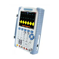
5.7 Signal Connectors
See the figure below to find the two signals connectors and a pair of metal electrodes at the
bottom of the oscilloscope panel.
1. CH1, CH2: Input connectors for waveform display, through which to connect and input the
signal to be measured.
 Loading...