8
※ Display range : -5 % ~ +105 % of range *1 : below 0 ℃ : ±0.2 % of F.S ±1digit
*2 : 0 ~ 400 ℃ : ±5 % of F.S ±2digit
●
Control output type
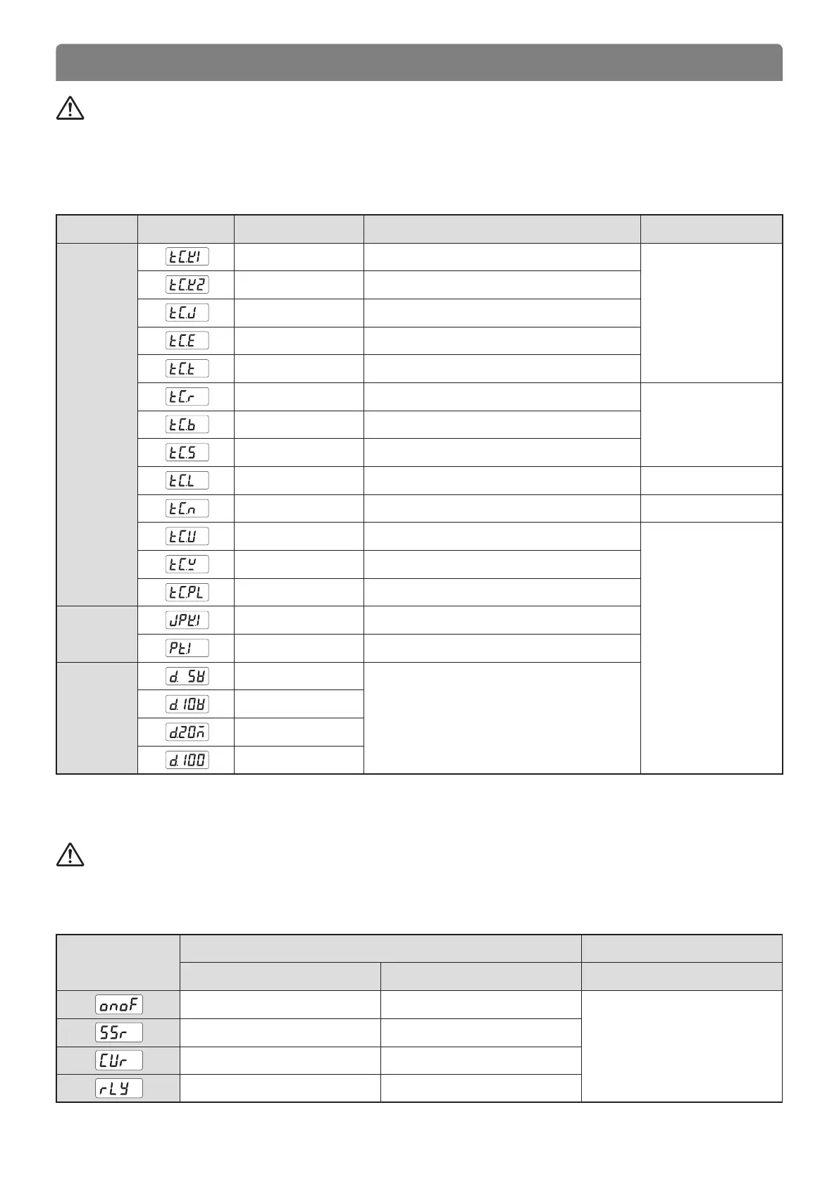
● Input type and Measurement range
※ ① ~ ⑦ : Terminal number
Caution
● Measurement Input Wiring
- When wiring the input line, cut off the controller and the external power.
- Be careful with polarity and wire the input signal at some interval from power circuit and ground connection circuit.
- Use shielded input cable when wiring and earth the shield 1 point.
5. INPUT & OUTPUT
Input type Code Input Range (℃) Accuracy
Thermocouple
(T.C)
K *1 -200 ~ 1370
±0.10 % of F.S
±1digit
K *1 -199.9 ~ 999.9
J *1 -199.9 ~ 999.9
E *1 -199.9 ~ 999.9
T *1 -199.9 ~ 400.0
R 0 ~ 1700
±0.15 % of F.S
±1digit
B *2 0 ~ 1800
S 0 ~ 1700
L *1 -199.9 ~ 900.0
±0.1 % of F.S ±1digit
N -200 ~ 1300
±0.2 % of F.S ±1digit
U *1 -199.9 ~ 400.0
±0.1 % of F.S
±1digit
W 0 ~ 2300
PlatinelⅡ 0 ~ 1390
RTD
JPT100 -199.9 ~ 500.0
PT100 -199.9 ~ 640.0
Direct
voltage
1 - 5 V **
Scaling range
SL-L ~ SL-H = -1999 ~ 9999
**When using current input, use the resistor
250 Ω 0.1 % on input terminal to use
4 - 20 mA DC input.
0 - 10 V
-10 - 20 mV
0 - 100 mV
Caution
● Control output wiring
- In case of wiring or eliminating the control output, cut off the controller and the external power.
- Use a shielded line for SSR pulse or Current output when wiring.
Output symbol
Control output (OUT1) Control output (OUT2)
Relay output SSR / SCR (Current) RET / SPS
ON–OFF control* ① - ② - ③
RET(Retransmission output) /
SPS(External power supply)
⑥ - ⑦
SSR ④ - ⑤
SCR ④ - ⑤
Relay ① - ② - ③

 Loading...