EasyManua.ls Logo

Happ 27 - User Manual

Default Icon
49 pages
Print Icon
To Next Page IconTo Next Page
Loading...
INSTALLATION
and
OPERATION MANUAL
FOUR POST WORKSHOP HOIST
HAPP27
The manual is an integral part of the lift, which it should always accompany even if the unit is sold. The
manual must be kept in the vicinity of the lift in an easily accessible place so that the operator and

Questions and Answers

  • J
    Jeremy SmithJul 28, 2025
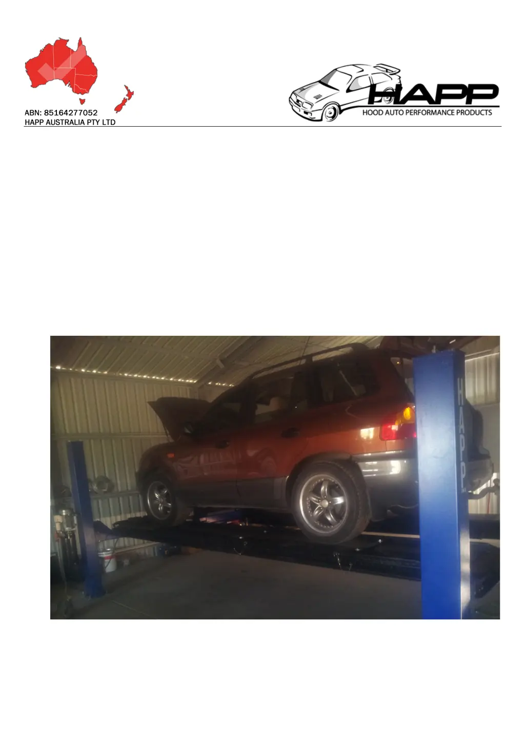
    What to do if my Happ 27 Lifting Systems only ascends and cannot descend?
    • D
      Daniel BennettJul 28, 2025
      If your Happ Lifting Systems only ascends but cannot descend, there could be several reasons: * The bleed valve may be too tight. Try adjusting it out in ½ turn increments until the hoist descends. * There might be a connection issue in the button. Inspect the button. * The electromagnetic valve could be blocked or unopened. In this case, you should check or change the electromagnetic valve. * If it's winter, the hydraulic oil might be too dense. Add oil according to the manual's instructions.
  • J
    Janet ThompsonAug 2, 2025
    Why does my Happ Lifting Systems engine rotate but the lift won't ascend?
    • R
      Reginald SmithAug 2, 2025
      If your Happ Lifting Systems engine rotates, but the lift does not ascend, it could be due to a few reasons: * There might be dust in the electromagnetism valve. Check and clean the electromagnetism valve. * The line pole could be loose. Make sure to fix it. * It's also possible that the hydraulic oil is falling short. Refill it with hydraulic oil.
  • J
    Jeffery ClarkAug 7, 2025
    What causes shaking in Happ 27 during operation?
    • A
      Ariana MendozaAug 7, 2025
      If your Happ Lifting Systems shakes during operation, it might be due to: * Air in the hydraulic pressure loop. You can release the air by redoing the ascend and descent. * An air leak at the top connect oil tube mouth of the pump. Check the seal of the oil tube mouth. * A jammed filtrate net. Clean the filtrate net.
  • F
    fbrownAug 11, 2025
    How to fix a Happ 27 when the engine doesn’t rotate?
    • C
      chadrossAug 11, 2025
      If the engine of your Happ Lifting Systems doesn’t rotate, consider the following: * There might be bad contact of wires. Check or change the contacts. * If installed, the contact wires for the optional limit switch might not be bridged. Adjust or change the limited switch if installed, or bridge wires out of the motor. * There could be bad action of the limit switch (if installed). Check the electromagnetism valve and clean it.
  • A
    Albert ChangAug 17, 2025
    Why is the ascend speed slow on my Happ 27?
    • G
      Gina WeberAug 17, 2025
      If the ascend speed of your Happ Lifting Systems is slow, it might be due to a leaking oil seal hole. In this case, you should change the oil seal.
  • B
    boydkimberlyAug 22, 2025
    What to do if I see an oil leak in my Happ Lifting Systems?
    • A
      austinlopezAug 22, 2025
      If you notice an oil leak in your Happ Lifting Systems, it is likely due to a loose fitting. Gently screw the fitting in.

Summary

Early Adopter Comments

Removal of this section

Customer reported catch on bumpers; inspection needed.

Length of Runways

HAPP27 runway length is 4.6m; measure for optimum location.

Safety release mechanism

Do not force; move release level and review operation.

Important Notes and Safety First

Electrical wiring

Follow electrical wiring notes in manual.

Oil grade

Hoist needs 10-15 litres of ISO grade 46 oil.

Anchor bolts

Use high quality masonry bit, check fit before purchasing.

Limit switch wiring

Connector available for limit switch option.

Safety first - ALWAYS

Responsible for installation, maintenance, safe operation; follow safety tips.

Introduction and Safety Instructions

Intended Use

Lift designed for safe lifting of automotive vehicles; observe load capacity.

Safety Instructions for Commissioning

Install and commission by authorized personnel only; avoid flammable areas.

Safety Instruction for Operation

Read operating instructions before use; lift operation by authorized personnel.

Workplace Health and Safety (WH&S) Overview

Servicing overview

Maintenance by authorized personnel; turn off power before work; use certified electricians.

Warranty and Maintenance

Warranty

Warrant products against faulty workmanship for one year; parts only basis.

General maintenance

Check lift, engage locks, check transmission, oil wheel shaft, change oil seasonally.

Purpose, Characteristics, and Main Parameters

Main parameters

Details model, capacity, dimensions, time, power, voltage, pressure, weight, noise.

Storage and Steel Frame Opening

Storage

Keep machinery nut in covered, protected place between -10°C and +40°C.

Opening the steel frame

Check for transport damage, ensure all parts present, use precautions to avoid damage.

Transportation and Installation Overview

Transportation; delivery

Package bolted with belt, control unit separate; move with forklift.

Installation overview

Take machine from packing, place on ground; pay attention to lift stability.

Installation Steps and Torque

Installation Torque Tinst

Check anchor bolt torque every six months; 80 Nm for HAPP 27.

Connecting the electrical power

Connect power supply.

Adjust the machine

Lift platform 100-200mm, press unloading handle, repeat 4-5 times.

Hoist Delivery and Unloading Procedures

Unloading the hoist on delivery

Deliveries can be collected or delivered; use forklift or crane for 1.4Tonne+ lift.

Tilt tray truck unloading

Using tilt tray truck to unload into building, use boards for protection.

Unpacking and Parts Identification

Unpacking the hoist

Runways fixed to frames; columns, pump, beams are heavy; use protective board.

Smaller parts list

List of smaller parts unpacked.

Parts Identification and Runway Removal

Parts supplied with 4 post lift

Lists and describes parts numbered 1-10.

Removing the runways

Extend hydraulic ram, be aware of oil leakage.

Hoist Assembly Steps

Assembling the hoist

Follow basic steps: place cross beams, assemble runways, place columns, attach cables.

Runway to Crossbeam Assembly

Place the cross beams on blocks

Important for easier cable installation; raise runways and move cross beams.

Assemble the runways onto the crossbeams

Lower runways, slide pulley into position; cannot lower main runway directly.

Column Placement and Attachment

Installing of slave runway

Lowering slave runway into position; install guide plates.

Place the columns onto the cross beams

Maneuver columns into position; install cables and safety mechanism.

Cable and Safety Mechanism Attachment

Attach cables and safety mechanism

Thread cable around pulleys, use tie wire to pull through.

Column Alignment and Securing

Align columns into correct position in building

Measure column location from edges, compare to plans.

Ensure the columns fit tightly onto nylon blocks

Nylon blocks must fit tightly to prevent sideways runway movement.

Measurements and Column Bolting

Double check all measurements

Verify measurements before drilling; difficult to modify location once drilled.

Bolt in columns

Use 18mm Tru bolts and 18mm masonry bit; tension to 80nM.

Drilling Tru Bolts and Pump Assembly

Process for drilling tru bolts

Drill through concrete if possible; drive tru bolts with heavy hammer.

Fit pump assembly

Easier to fill off-line using automatic transmission filler funnel.

Safety Mechanism Connection

Adjust cables and safety mechanism

Connect safety mechanism via steel tube; attach ends using bolts and pins.

Safety Latch Bar Adjustment

Centering the safety latch bar

Use adjustment in column base to center safety latch bar with catches.

Test safety mechanism operation

Test fluid operation, lower lever for latches out, raise lever for engaging.

Cable and Safety Latch Height Adjustment

Adjustment nuts at top of column

Used for cable and safety latch height adjustment.

Setting cable adjustment

Lift hoist, measure beams, adjust until within 10mm; safety latches engage together.

Operating Environment and Working Conditions

Working conditions

Ambient temperature 5-40°C, humidity 30-95%, transportation temp 25-55°C, max altitude 1000m.

Hoist Operation Procedures

Operation - Lift operation by authorized personnel

Lift operation by authorized personnel over 18 years only.

Hoist Operating Procedures

Product designed to raise vehicles for examination, repairs, maintenance.

Pre operation checks

Ensure manuals read, maintenance done, check fittings, bolts, foundations, safety mechanisms, cords, cables, pads, arm locks.

Operation: Raising;Lowering and Maintenance

Operation: Raise

Ensure personnel clear, push green button to raise, engage safety latches.

Operation: Lower

Ensure personnel clear, push green button to raise slightly, disengage safety latches, use unloading handle.

Maintenance

Follow user guides for planned maintenance, isolate circuits before work.

Maintenance Schedule and Environmental Considerations

Maintenance Schedule

Weekly checks for support template, anchor bolts; 3-monthly for greasing points; 12-monthly for hydraulic system.

Environment

Hoist not for outside, steam cleaning, high moisture; only registered hoists for business premises.

Defects;Malfunctions and Control Unit

Defects;Malfunctions

Jerky lift movement or deformation; turn off power, contact service personnel.

Controls - Power unit

Controls include green button for up, unloading handle for down; adjust speed and pressure.

Electrical System Overview

Electrical system

Illustrates electrical connections for control unit on electric motor.

Limit Switch Wiring Details

Limit switch wiring (optional)

Shows limit switch wiring inside single phase motor.

Electrical Connections and AS3000 Standard

Electrical connection to motor

White connector for optional limit switch; bridge wires to disable if not used.

Electrical wiring - AS3000

Power wiring follows Australian standard AS3000; verify connections.

Vehicle Loading and Raising

Loading vehicle onto lift

Lower platform, position vehicle, apply parking brake, leave vehicle clear.

Raising

Position vehicle, check security, ensure clear, place pads, connect power, press green button to raise.

Vehicle in Raised Position and Lowering

Vehicle in raised position

Observe regulations, ensure safety latches engaged, no unauthorized persons, avoid rocking.

Lowering

Ensure safety area clear, raise slightly to clear safety, release safety latch handle, press unloading handle to lower.

Troubleshooting Common Issues

Engine doesnt rotate

Causes and solutions for engine not rotating.

Engine rotates but lift does not ascend

Causes and solutions for lift not ascending.

The ascend speed is slow

Causes and solutions for slow ascent speed.

Shake in the running

Causes and solutions for shaking during operation.

Only ascend, cannot descend

Causes and solutions for inability to descend.

Oil leak

Causes and solutions for oil leaks.

Hydraulic System Components and Diagram

Hydraulic System Components

Lists and diagrams components of the hydraulic system.

Reference Diagram for Installation

Reference numbers for hoist discussion

Figure for discussing installation, shows HAPP 28 with extra parts.

Safe Operation Guidance

To customers

Providing specific information for installation, operation, maintenance; offering help.

Operator Responsibility for Safe Operation and Installation

Owners responsibility for installation and operation

Owner responsible for installation, operation, regulations, and personnel training.

Happ 27 Specifications

General IconGeneral
BrandHapp
Model27
CategoryLifting Systems
LanguageEnglish