EasyManua.ls Logo

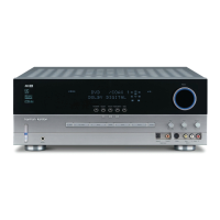
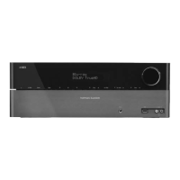
Harman Kardon AVR 139/230 User Manual

Harman Kardon AVR 139/230
83 pages
To Next Page IconTo Next Page
Page #1 background imageLoading...
Page #1 background image
harman/kardon Service Manual
AVR 139/230
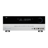
AVR 141/230
AVR 142/230
5 x 40W 5.1 CHANNEL A/V RECEIVER
CONTENTS
ESD WARNING 2
BASIC SPECIFICATIONS 3
TROUBLESHOOTING GUIDE 4
PROCESSOR RESET 4
PACKAGE LISTS AND PARTS 5
DISASSEMBLY 8
EXPLODED VIEW AND PARTS 9
ELECTRICAL PARTS LIST 10
IC LIST 30
SEMICONDUCTOR PINOUTS 31
PCB DRAWINGS 69
BLOCK DIAGRAM 74
WIRING DIAGRAM 75
AMP BIAS ADJUSTMENT 76
SCHEMATIC DIAGRAMS 77-83
Released EU2009 Harman Consumer Group, Inc. Rev 0, 04/2009
8500 Balboa Boulevard
Northridge, California 91329
Question and Answer IconNeed help?

Do you have a question about the Harman Kardon AVR 139/230 and is the answer not in the manual?

Harman Kardon AVR 139/230 Specifications

General IconGeneral
BrandHarman Kardon
ModelAVR 139/230
CategoryReceiver
LanguageEnglish

Summary

Safety Precautions

Electrostatically Sensitive Devices (ES)

Guidelines for handling semiconductor devices to prevent static discharge damage.

Product Safety Notice

Important safety notices for servicing and component replacement.

Technical Specifications

Audio Section Specifications

Details on Stereo and Surround sound output power, and input sensitivity.

Tuner and Video Specifications

Specifications for FM/AM tuners and video input/output.

General Specifications

Information on power requirements, dimensions, and weight.

Troubleshooting Guide

Processor Reset Procedure

Steps to reset the unit's memory and processor to clear system malfunctions.

Parts and Packaging

Accessory List and Package Drawing

Lists included accessories and provides package drawings for identification.

Disassembly

Exploded View and Parts

Electrical Parts Lists

Model-Specific Parts Lists

Detailed electrical parts lists for AVR 139, 141, and 142 models.

PCB Component Details

Front PCB Assembly Components

Lists components for the Front PCB Assembly.

IC List

Semiconductor Component Datasheets

Voltage Regulator ICs

Datasheets for various voltage regulator ICs.

Digital Logic IC Datasheets

Datasheets for Hex Inverter ICs.

Audio IC Datasheets

Datasheets for operational amplifier ICs.

Memory and Interface IC Datasheets

Datasheets for memory and interface ICs.

Transistor Datasheets

Datasheets for various transistors.

Microcontroller Datasheets

T5CC1 Microcontroller Pinout

Pin assignment diagram for the T5CC1 microcontroller.

T5CC1 Pin Functions

Detailed description of the T5CC1 microcontroller pin names and functions.

PCB Layout Diagrams

AVR139 Front PCB Layout

Layout diagram for the AVR139 front PCB.

CUP12109Z PCB Layout

Layout diagram for the CUP12109Z PCB.

Wiring Diagrams

AVR139 Wiring Diagram

Diagram illustrating the wiring connections for the AVR139 unit.

Block Diagrams

AVR139 Block Diagram

Overall block diagram of the AVR139 unit.

Service Adjustments

Amplifier Bias Adjustment

Procedure for adjusting amplifier section bias settings.

Schematic Diagrams

CUP12185Z Schematic Diagram

Schematic diagram for the CUP12185Z circuit board.

CUP12109Z Schematic Diagram

Schematic diagram for the CUP12109Z circuit board.

AVR139/230 Schematic Diagram

Overall schematic diagram for the AVR139/230 unit.
Related product manuals