TC90A49P/F
PIN
No.
PIN NAME FUNCTION I / O INTERFACE
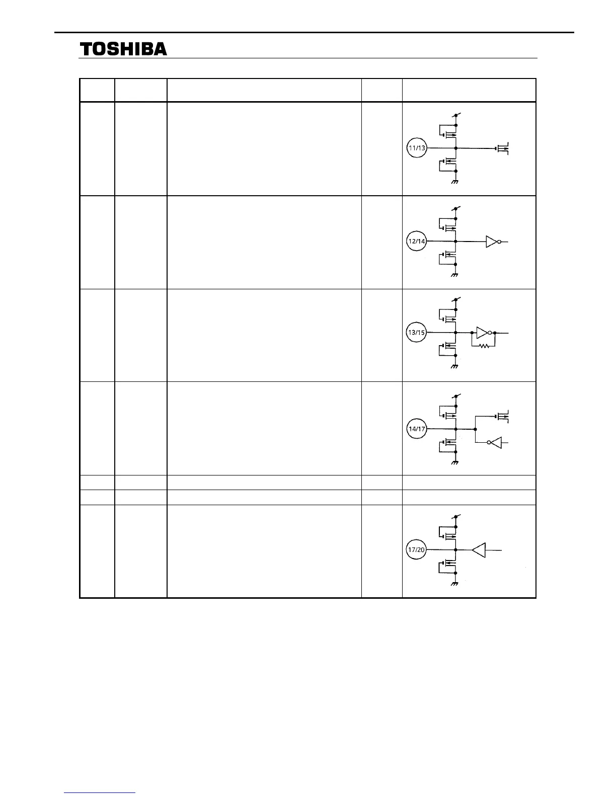
11 / 13 TEST
Shipment test mode switch or I
2
C bus setting reset pin.
When High, test mode, setting all I
2
C bus settings to 0.
Hold High for at least 100µs. Send I
2
C bus settings
when this pin is Low.
I
12 / 14 KILLER
Y signal comb function ON / OFF switch.
When High, comb OFF. When Low, comb ON. When
[data 3 : bit 0] is 1, used as vertical edge enhancement
circuit ON / OFF switch.
I
13 / 15 CKIN
Clock input pin. Pin 13 put a sine wave which is locked
to the frequency of the burst signal in the input video
signal. Amplitude is 300 mV
p-p
to 2 V
p-p
. Input as high
an amplitude as possible without affecting peripheral
circuits.
I
14 / 17 FIL Connect the APC filter in the 8 fsc PLL circuit. −
15 / 18 V
DD1
PLL power supply. − −
16 / 19 V
SS1
ADC, DAC, and PLL GND (analog). − −
17 / 20 C
OUT
Outputs chrominance signal. External simple LPF for
clock elimination recommended.
O
AVR340 harman/kardon
 Loading...