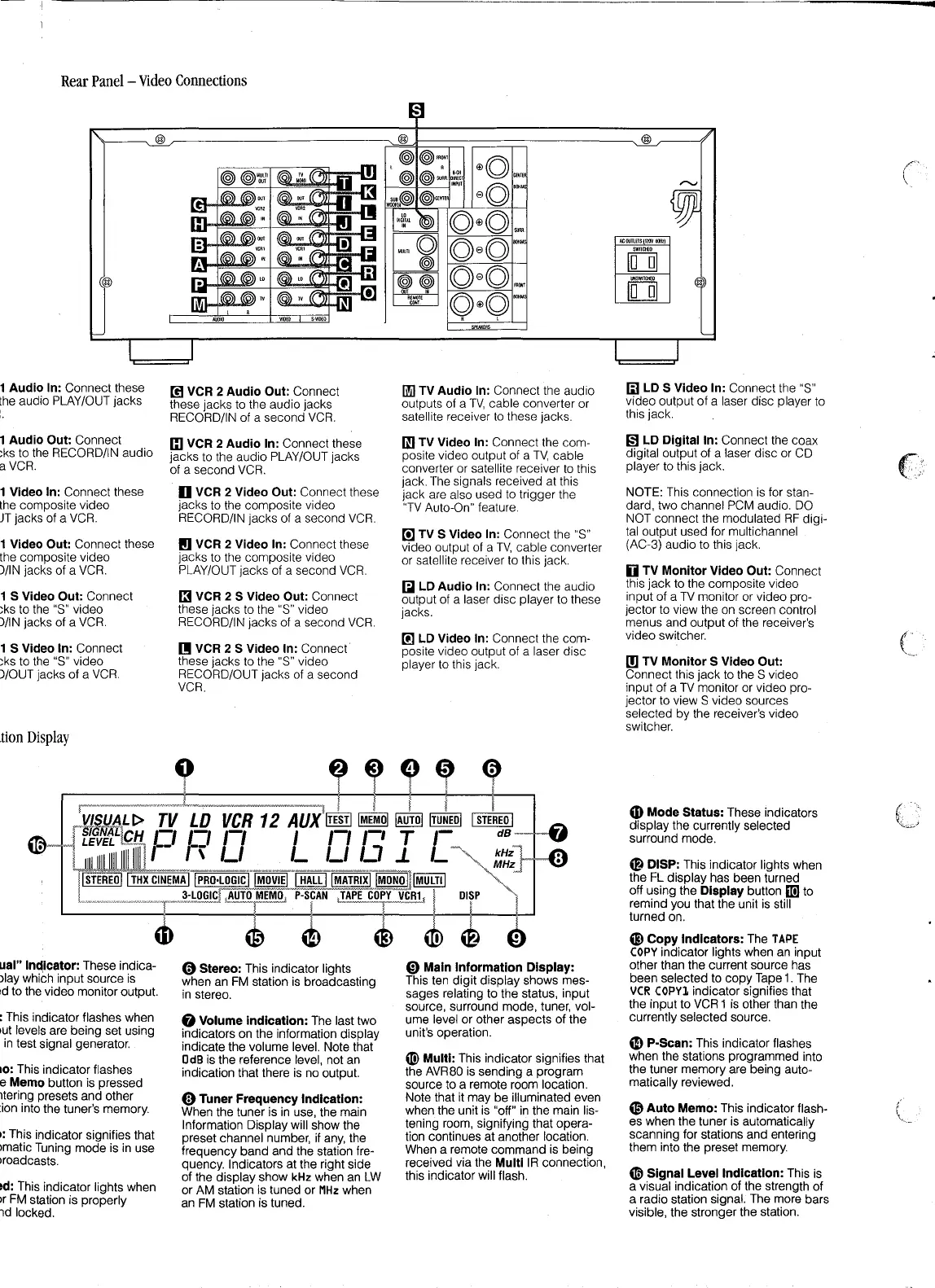
Rear
Panel
-
Video
Connections
1 Audio In: Connect these
the
audio PLAY/OUT jacks
1 Audio Out: Connect
:ks to the RECORD/IN audio
a
VCR.
1 Video In: Connect these
the composite video
JT
jacks of a
VCR.
1 Video Out: Connect these
the composite video
)/IN jacks of a
VCR.
1 S Video Out: Connect
;ks to the
"S"
video
)/IN jacks of a
VCR.
@
1 S Video In: Connect
;ks
to the "S" video
)/OUT jacks of a
VCR.
.tion
Display
ual" Indicator: These indica-
Jlay which input source
is
1d
to the video monitor output.
: This indicator flashes when
>ut
levels are being set using
:
in
test signal generator.
10: This indicator flashes
e
Memo button is pressed
1tering presets and other
lion into the tuner's memory.
1:
This indicator signifies that
Jmatic Tuning mode
is
in
use
Jroadcasts.
td: This indicator lights when
Jr
FM
station is properly
nd locked.
00
VCR 2 Audio Out: Connect
these jacks to the audio jacks
RECORD/IN of a second
VCR.
Cl
VCR 2 Audio In: Connect these
jacks to the audio PLAY/OUT jacks
of a second
VCR.
D VCR 2 Video Out: Connect these
jacks to the composite video
RECORD/IN jacks of a second
VCR.
(g
VCR 2 Video In: Connect these
jacks to the composite video
PLAY/OUT jacks of a second
VCR.
(3
VCR 2 S Video Out: Connect
these jacks to the "S" video
RECORD/IN jacks of a second
VCR.
[I
VCR 2 S Video In: Connect
these jacks to the "S" video
RECORD/OUT jacks of a second
VCR.
0 Stereo: This indicator lights
when an
FM
station
is
broadcasting
in
stereo.
@ Volume indication: The last two
indicators on the information display
indicate the volume level. Note that
□
dB
is the reference level, not an
indication that there
is
no output.
0 Tuner Frequency Indication:
When the tuner is
in
use, the main
Information Display will show the
preset channel number, if
any,
the
frequency band and the station fre-
quency. Indicators at the right side
of the display show
kHz
when an
LW
or AM station is tuned or
MHz
when
an
FM
station is tuned.
li!i)
TV Audio In: Connect the audio
outputs of a
TV,
cable converter or
satellite receiver
to
these jacks.
I]] TV Video In: Connect the com-
posite video output of a
TV,
cable
converter or satellite receiver to this
jack. The signals received at this
jack are also used to trigger the
"TV
Auto-On" feature.
[!]TVS
Video In: Connect the "S"
video output of a
TV,
cable converter
or satellite receiver to this jack.
[;I
LD Audio In: Connect the audio
output of a laser disc player to these
jacks.
[!] LD Video In: Connect the com-
posite video output of a laser disc
player to this jack.
0 Main Information Display:
This ten digit display shows mes-
sages relating to the status, input
source, surround mode, tuner, vol-
ume level or other aspects of the
unit's operation.
«!)
Multi: This indicator signifies that
the AVR80
is
sending a program
source to a remote room location.
Note that it may be illuminated even
when the unit is "off"
in
the main lis-
tening room, signifying that opera-
tion continues at another location.
When a remote command is being
received via the
Multi
IR
connection,
this indicator will flash.
(;)
LD S Video In: Connect the
"S"
video output
of
a laser disc player to
this jack.
1§)
LD Digital In: Connect the coax
digital output of a laser disc or CD
player to this jack.
NOTE: This connection
is
for stan-
dard, two channel PCM audio. DO
NOT connect the modulated
RF
digi-
tal output used for multichannel
(AC-3) audio to this jack.
D
TV
Monitor Video Out: Connect
this jack to the composite video
input of a
TV
monitor or video pro-
jector to view the on screen control
menus and output of the receiver's
video switcher.
[!)
TV
Monitor S Video Out:
Connect this jack to the S video
input of a
TV
monitor or video pro-
jector to view S video sources
selected by the receiver's video
switcher .
4D
Mode Status: These indicators
display the currently selected
surround mode.
@ DISP: This indicator lights when
the FL display has been turned
off using the
Display button
mJ
to
remind you that the unit
is
still
turned on.
@ Copy Indicators: The
TAPE
COPY
indicator lights when an input
other than the current source has
been selected to
copy
Tape
1.
The
VCR
COPY1
indicator signifies that
the input to
VCR
1
is
other than the
currently selected source.
a, P-Scan: This indicator flashes
when the stations programmed into
the tuner memory are being auto-
matically reviewed.
© Auto Memo: This indicator flash-
es when the tuner is automatically
scanning for stations and entering
them into the preset memory.
([ii
Signal Level Indication: This
is
a visual indication of the strength of
a radio station signal. The more bars
visible, the stronger the station.
C
C
 Loading...