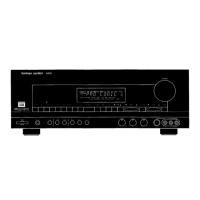
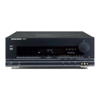
Figure 3
This view of the unit shows the connections from the 3-channel amp assembly to the main PC board (See
Figure 3). Note that 3 connections on Main PCB board are the same size, and use the same color
wires. These connections CAN BE INTERCHANGED if not careful and serious damage can occur if the
technician is not careful.
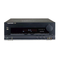
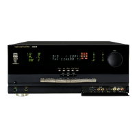
Figure 4
Be careful not to break any of the contacts, wires, or sub assemblies. The PC boards shown in the above
picture (Figure 4) are all interconnected through four separate extender boards. If you look carefully at the
stacked PC boards, you will notice that when they are not in the chassis with the rear plate attached, they are
NOT supported at one end. This may cause a Short to occur if one PC board touches another while the unit is
being serviced.
AVR8000
harman/kardon
 Loading...