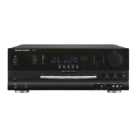
Figure 5
Another view of the sub assemblies (Figure 5). There are 2 sets of connecting “fingers” that have NO key
way. Some of the PC boards can be interchanged with each other, and if not careful, could be installed wrong.
The technician should, with the aid of the wiring diagram, draw a diagram of the connectors, where they
connect to each location on each sub-assembly, and if necessary, mark the connectors with a tag so they do
not get mixed up.
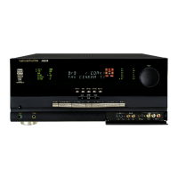
Figure 6
The fuses shown in Figure 6, are on the bottom PC board in the center stack ( See Figures 4 & 5). To view
or access: remove the top cover, rear panel, the center stack of PC boards, and disassemble the stack.
Once this is accomplished, the technician should check the fuses for continuity, troubleshoot the cause of the
short, repair the problem, replace the fuse, then reassemble the unit to check and see if it is functional.
AVR8000
harman/kardon
 Loading...