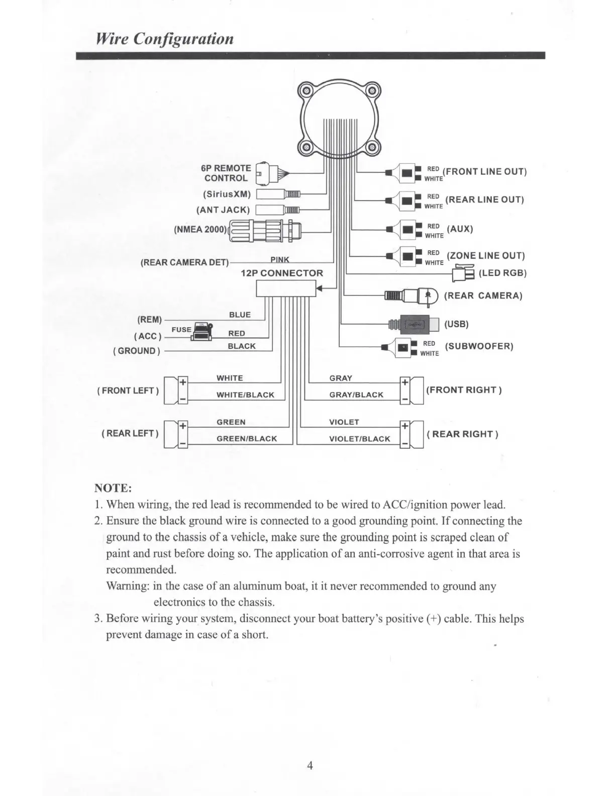
Wire Configuration
6P
REMOTE
CONTROL
(Si ri u
sXM)
c=:nnnm---_J
(NMEA2000)
(REAR CAMERA DET)
---
L..W""-
--
--'
12P
CONNECTOR
(REM)
----===----
_ B_L_U_E~
(ACC)
- -IJ!!!!~-R~E=D;.._____.
(GROUND)-----B_LA_C_K_~
WHITE
(
FRONT
LEFT
)
WHITE/BLACK
GREEN
(
REAR
LEFT)
GREEN/BLACK
NOTE:
GRAY
GRAY/BLACK
VIOLET
VIOLET/BLACK
RED
(FRONT
LINE
OUT)
WHITE
RED
(REAR
LINE
OUT)
WHITE
RED
(ZONE LINE OUT)
WHITE
(LED RGB)
(REAR
CAMERA)
(USB)
(SUBWOOFER)
(FRONT
RIGHT)
(
REAR
RIGHT)
1. When wiring, the red lead is recommended
to
be wired to A CC/ignition power lead.
2. Ensure the black ground wire is connected to a good grounding point.
If
connecting the
ground to the chassis
of
a vehicle, make sure the grounding point is scraped clean
of
paint and rust before doing so. The application
of
an anti-corrosive agent in that area is
recommended.
Warning: in the case
of
an aluminum boat, it it never recommended to ground any
electronics to the chassis.
3. Before wiring your system, disconnect your boat battery's
positive(
+) cable. This helps
prevent damage in case
of
a short.
4