6
3-90-08101R23_06/13
Assembly
Assembling Filter Box, Cont’d
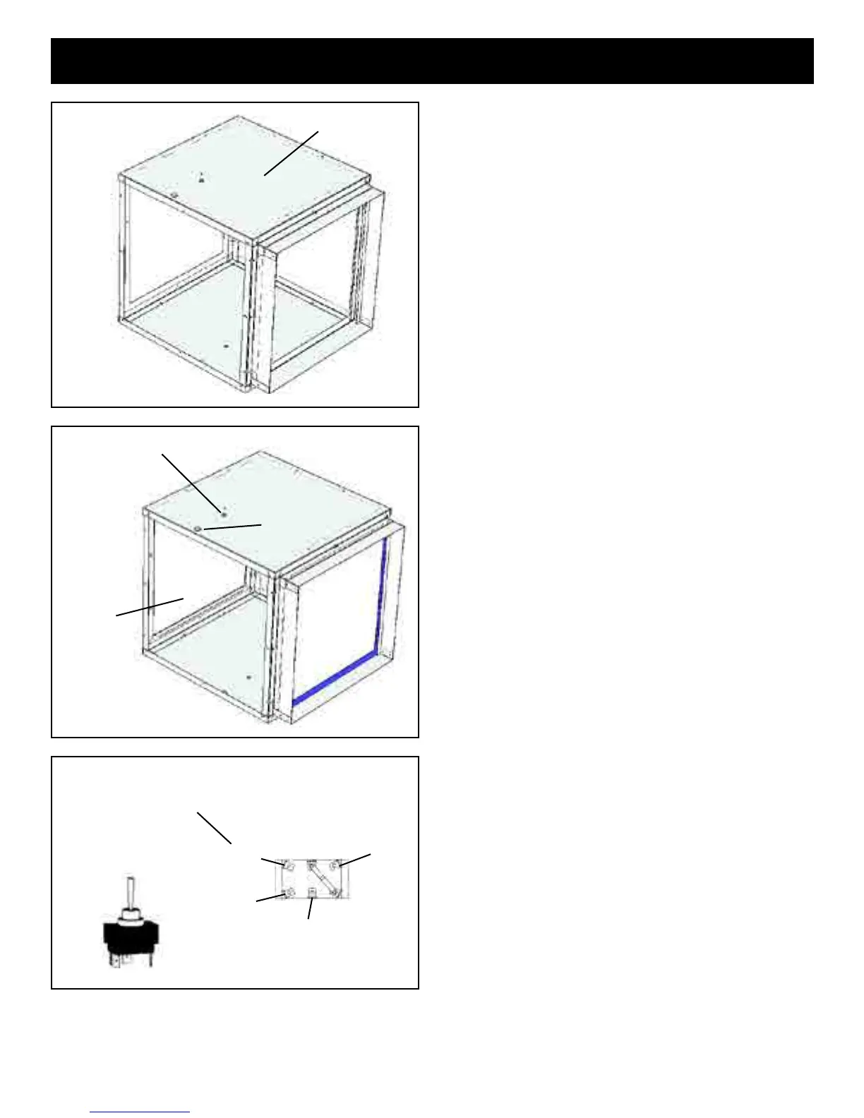
5. Placethetoponthelterboxasshowningure8.A
tthistime
allTekscrewscanbeinsertedaroundthelterbox.
Note: Exceptforthe(6)screwsthatattachthebloweraccess
panelinplace.
Thereshouldnotbeanyscrewsprotrudingfromtheboxon
thesidetowardthefurnace.AlsoDONOTputascrewinto
thetopcenterofthelterpanelasascrewinthislocation
willinterferewiththelteraccesscover.
6. Pryoutthetwoknockoutsinthetopoftheboxandinstall
theexconnectorandtheswitch.SeeFig.9.
Note: Don’tforgettheHI-MED-LOswitchlabelontheswitch
beforethelocknut.Makesurethatthesetscrewontheex
connectorisnotpointingtowardthefurnaceendofthebox
whenthelocknutisfullytightened.Thelterboxisnowready
toinstallontothefurnace.
FollowtheBlowermountinginstructionsonpage7before
continuingtostep#7.
Note: Theblowershouldbemountedonthefurnacebefore
thelterboxforeaseofdistributionblowerinstallation.
Note:Itisbesttowaituntiltheblower,lterbox,andcold
airreturnductworkisinstalledbeforeinstallingthelterand
sidepanel.
7. AftertheFilterBoxisinstalledonthefurnacetheelectrical
wiringtothethreespeedswitchneedstobecompleted.
WhiteorPurpleNeutraltoWhiteNeutral,Violetfromthe
FanControltothecenterterminaloftheswitch,andthe
Black,Red,andBlueorYellowtotheterminalsshown.
Note:The1000CFMblowerisa3-speed,andwillwireas
shown.The 1450 CFM blower is a single speed blower,
thereforethethreespeedswitchwillnotbeused.The1638
CFMblowerisa4speed,onlyhookupthethreecolorsshown
andtapeofftheorangewire.SeeFig.10.
(Note: the purple wire on the 1638 cfm blower is neutral,
and gets spliced to the white neutral wire.)
8. Installtheaccesspanelcoverbyhookingthelipatthe
bottomofthecoverovertheedgeinthelterbox.Use6
Tekscrewstosecuretheaccesspanel.
9. Toinstallthelter,insertthelterintothelterslotand
slidecompletelyintotheframe.Takenotetotheairow
arrowonthelterwheninstalling.Slidethelteraccess
coverovertheopeningwiththeuprightangletowardthe
lterbox.IfaTekwasputintothemiddleholebymistake,
removethescrewtoallowtheaccesscovertotproperly.
Fig. 8
Top
Fig. 9
Access Panel
Cover opening
3 Speed Switch
Flex connector
Fig. 10
BOTTOM VIEW OF 3-SPEED SWITCH
Violet 120VAC
From fan control
Yellow on 1638 CFM motor
Blue
Med.
Black
High
Red
Low